01A CLEARER CASTING PURCHASE
Ductile-Iron Flanges with Finished Sealing Faces
Buy the flange around the connection that must locate and seal. Relia offers ductile-iron components with sand casting and CNC machining, including nominated face, pilot, bore and bolt-pattern work. Keep those relationships with the selected grade and mating definition. Your quotation can then describe the usable joint interface rather than a flange-shaped blank.
- Material
- Selected ductile iron
- Production
- Sand casting + CNC
- Connection
- Face, central fit + bolts
02A CLEARER CASTING PURCHASE
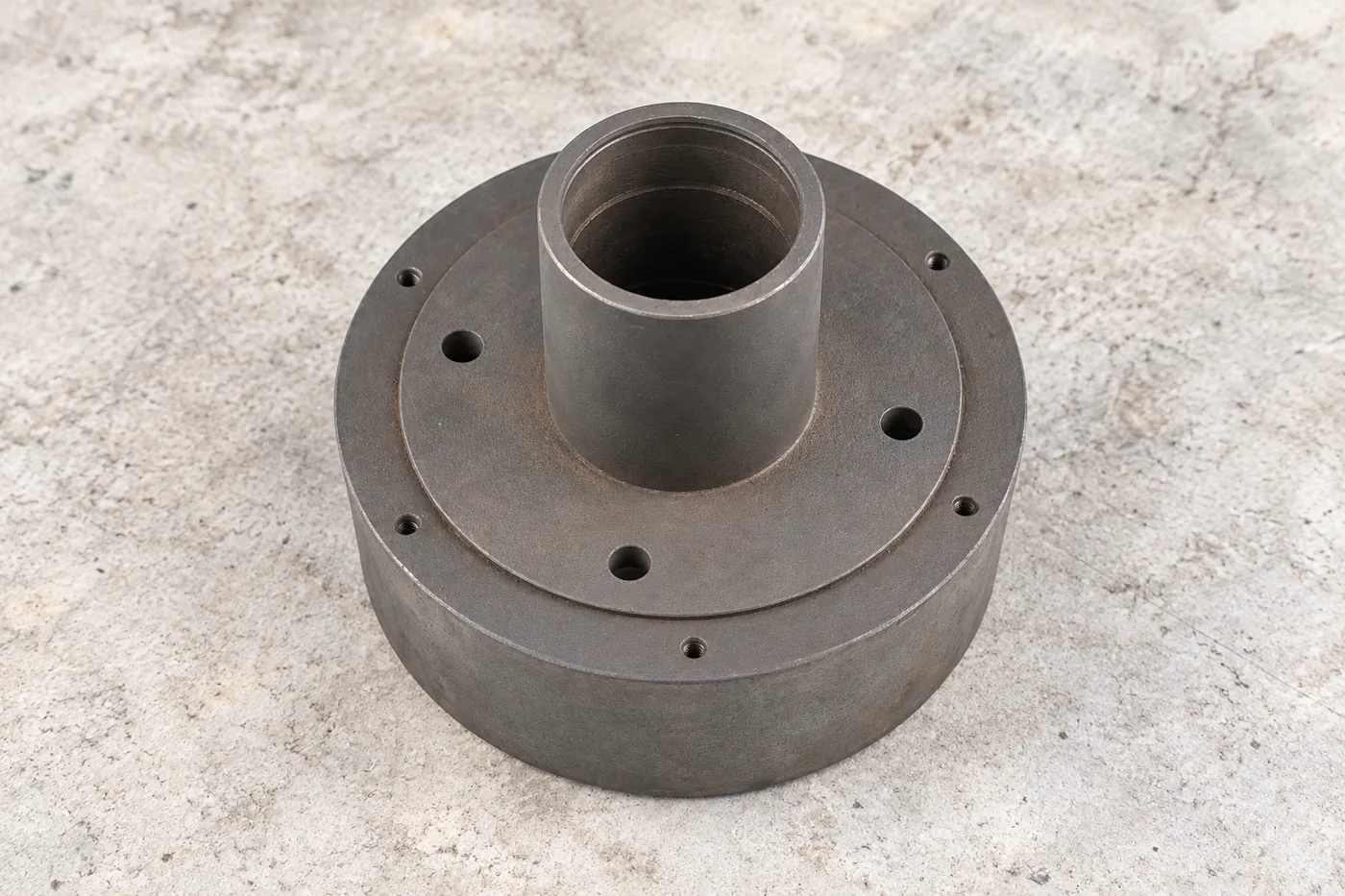
Flange blanks and CNC connection features supplied together
Relia Casting's flange offer includes OEM/ODM dimensions, drawing-based tolerances and 100% inspection for the actual component. We have our own sand-casting and machining production, with coated-sand/shell as the main factory route and the SKU route selected from its drawing. Material and dimensional reports and real workshop photographs are available for assessment.
A flange may follow a named standard or be a custom machinery joint. Its central pilot or bore can locate the connection while holes provide fastener clearance. We keep those roles distinct so the machined face and pattern relate to the feature your assembly actually uses for centring.
03A CLEARER CASTING PURCHASE
The bolt circle and central fit share a datum scheme
Specify hole count, diameter, pitch-circle geometry and clocking from the selected datum references. Include clearance for fasteners and tools. If a pilot locates the joint, relate the hole pattern and face to that pilot rather than measuring from an arbitrary outside edge.
The same drawing should identify the central bore, hub length and any axial shoulder. A flange can meet individual size limits yet fail to assemble when the pattern is misplaced relative to its locating feature. Prioritise these relationships in the CNC and inspection plan.
| Functional feature | What the drawing should control |
|---|---|
| Fastener pattern | Count, hole size, circle/location and clocking |
| Central interface | Bore or pilot size, fit and usable contact length |
| Axial geometry | Hub/shoulder length and mating-face position |
| Datum relationship | Face and pattern relative to the centring feature |
04A CLEARER CASTING PURCHASE
A sealing face chosen for the actual gasket
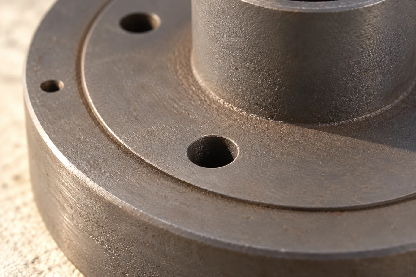
Specify the usable sealing land, surface texture and face geometry required by the joint design. A shiny face is not a universal sealing improvement. Sealing-association guidance treats face finish, gasket characteristics and clamping as related parts of the joint.
Identify interruptions, bolt holes and edges that affect gasket contact. Keep protective paint or preservative off final contact areas where required, and specify how it is removed before assembly. The inspection should assess the actual seal-supporting surface rather than only the flange outside diameter.
- Contact land
- Geometry and texture for the actual gasket
- Edges
- Interruptions and final protection boundaries
05A CLEARER CASTING PURCHASE
The ductile-iron requirement stays with this flange
Choose the complete ductile-iron grade, governing specification and supplied condition for the flange's mechanical and service requirements. Our listing also covers separate grey-iron roller parts; those are a different supply object, not an alternative material automatically applied to this joint.
Allocate material and dimensional acceptance to the actual flange. Where a pressure-service application is intended, retain the governing design and rating basis in the project specification. For a machinery connection, keep its load and fit conditions visible instead of assuming a pressure class from the flange shape.
06A CLEARER CASTING PURCHASE
Produce stock at the hub and finish the joint from stable datums
Pattern and parting choices establish the flange blank and its local sections. The hub-to-flange junction and any cast opening need usable stock at the future bore, pilot and face, with the feeding and transition proposal matched to that geometry. A broad outside allowance is less useful than metal at the final centring location.
After gate removal and cleaning, the CNC plan establishes stable references, finishes the central location and joint face, then relates the bolt pattern to them. The operation order should preserve the specified relationship when the part is repositioned. Inspect cast regions against the blank definition and the completed joint against its finished requirements. That yields a measurable connection geometry while retaining the selected ductile-iron section beneath it.
- 01Form the blankHub junction, parting and local stock
- 02Prepare referencesClean the casting and establish stable locators
- 03Machine the connectionRelate pilot/bore, face and bolt pattern
- 04Release the componentMaterial evidence plus finished joint-feature results
07A CLEARER CASTING PURCHASE
The connection checked as related features
Our flange listing states 100% inspection against the ordered component's requirements. Translate that into checks for the central fit, face geometry, pattern location and required material evidence. Record actual results against drawing features and identify the part or batch.
A mating trial can expose assembly interference, but it should complement the dimensional record. Where interchangeable spare flanges are required, state that requirement explicitly; fitting one selected counterpart does not define every later cross-fit. Keep approval connected to the intended stock and assembly arrangement.
- Inspection
- 100% component inspection scope
- Joint map
- Central fit, face and pattern results
08A CLEARER CASTING PURCHASE
Joint qualification follows the designed assembly
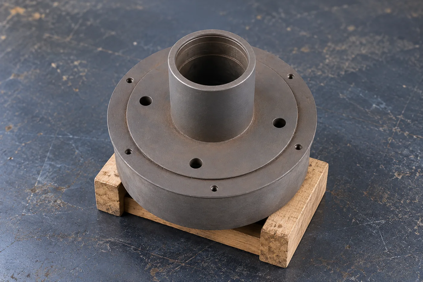
The flange, gasket, fasteners and mating part act together. Define the assembly instruction and any required pressure, leakage or mechanical evaluation at that joint level. The casting inspection answers whether the supplied flange meets its manufactured definition.
A useful test requirement identifies the actual assembly, medium or load, conditions and acceptance. Keep bolt-loading and gasket choices with the responsible joint design rather than inserting a generic torque into the flange purchase order. This makes the evidence useful without confusing a component check with a qualified complete connection.
- 0101Release compatible mating face, gasket and fastener definition
- 0202Accept material and finished flange geometry
- 0303Apply the specified assembly and joint-evaluation procedure
- 0404Retain the approved configuration for subsequent supply
09A CLEARER CASTING PURCHASE
Machined lands protected against contact damage
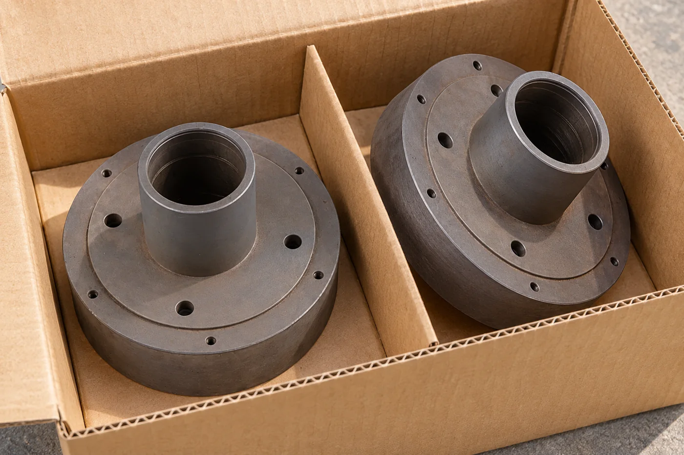
Separate flanges so their sealing lands and pilot edges cannot rub or strike adjacent parts. Protect finished surfaces from corrosion using the agreed temporary condition and keep openings free of packing debris. Identification should connect the arriving flange to its material and drawing revision.
Inspect the functional land and centring feature before assembly. A damaged edge or dent can alter the installed condition even when the original dimensions were accepted. Keeping protection tied to the drawing features helps your receiving team preserve the supplied joint geometry.
- Packing
- Separate sealing faces and pilot edges
- Receiving
- Part identity retained with material and revision
10A CLEARER CASTING PURCHASE
A flange purchase ready for its mating assembly
The package you buy should retain the selected iron, centring geometry, usable sealing land and fastening relationship in the final supplied condition. Relia can manufacture the sand-cast and CNC-finished flange around that outcome, with the sample inspection and your confirmation forming the starting point for batch production.
Keep the gasket and assembly instruction with the responsible joint design. The flange's dimensional record supports that assembly; a separate joint test answers its pressure, leakage or load requirement. This gives you a clear component comparison without turning a correct bore or face into an unperformed complete-joint qualification.
11 YOUR NEXT STEP
Bring your component into the conversation
Tell us which component you need, the material, quantity and required supplied condition. Relia will connect your enquiry with the casting, machining and evidence relevant to that part.
Technical reading and scope
Technical references explain the process. Component specifications and agreed order records define the actual supply.
ESA/FSA — flange and gasket joint principlesISO 8062-3 — casting tolerances and machining allowances- [email protected]
- Phone
- +86 18561762631
- +1 404 203 0971
- Company and address
- Qingdao Relia Industries Co., Ltd.
Shuyuan Road, Qingdao, Shandong, China