
01A CLEARER CASTING PURCHASE
Industrial Iron Flywheels for Defined Duty
Buy the flywheel as a controlled rotating component. Relia offers custom cast-iron enquiries with selected sand or resin-sand routes. Retain rim and hub geometry, shaft connection, material condition and operating speed in one release. The casting and finishing scope can then support the intended inertia and installation, rather than compare only diameter and total mass.
- Geometry
- Rim, hub + shaft fit
- Duty
- Defined operating speed
- Accept
- Required supplied state
02A CLEARER CASTING PURCHASE
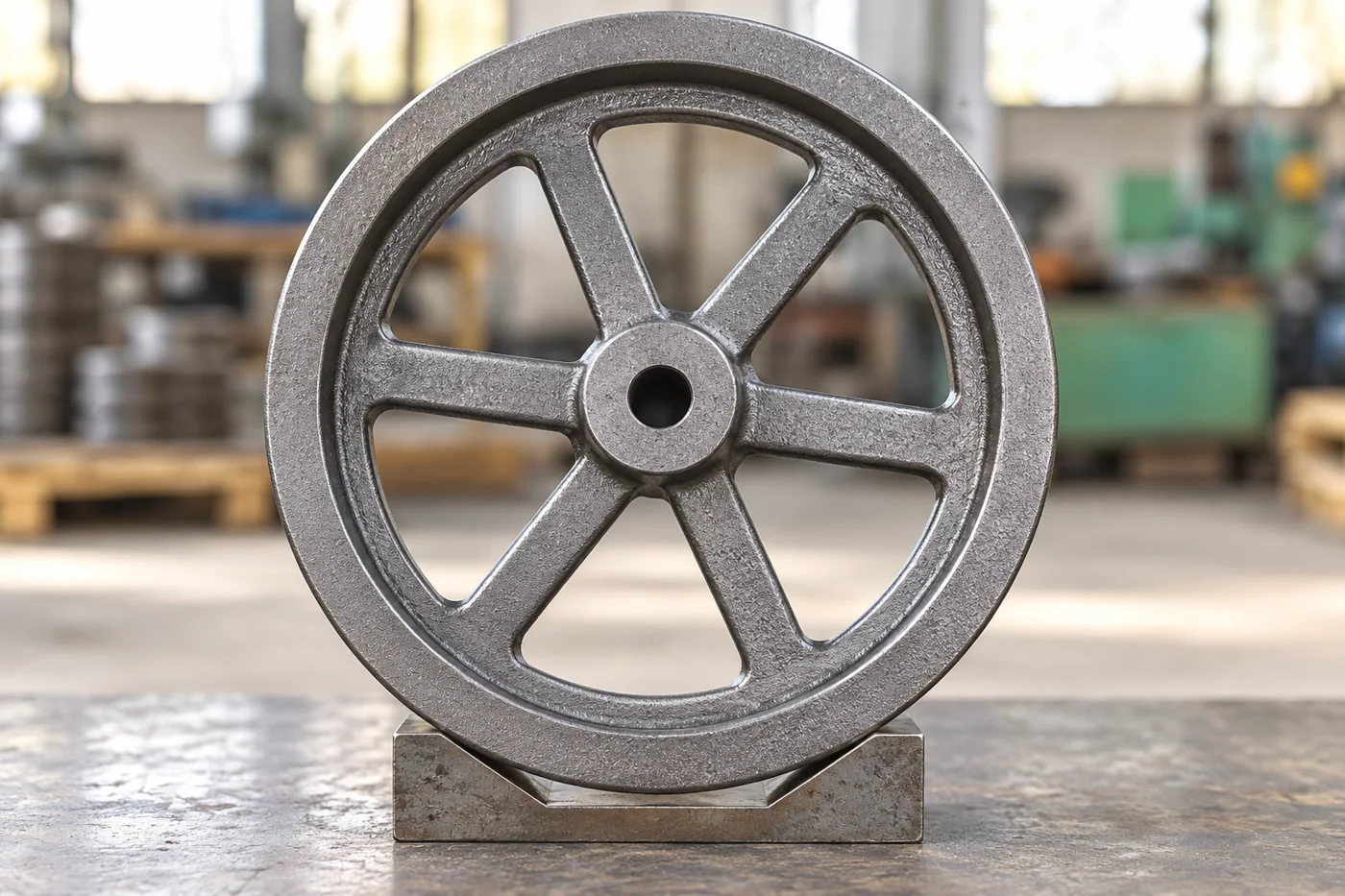
Iron flywheels with a defined mounting handover
Relia Casting offers custom industrial iron flywheels through sand- and resin-sand-casting enquiries, with samples available before an order. Our own machining production can complete nominated shaft and locating features within the agreed component package. The iron flywheel scope is distinct from the separate multi-metal or aluminum processes described elsewhere in the wider catalogue.
For your machine, the rim, web or spokes and hub are one rotating design. Energy follows E = ½Iω², so the distribution of metal matters as well as total mass. We preserve the released geometry and selected iron condition through manufacture; your design's speed and duty remain the basis for any specified rotating evaluation.
03A CLEARER CASTING PURCHASE
Iron and casting route stay separate from other metal requests
Our industrial flywheel catalogue offers cast iron through sand and resin-sand routes, with samples before order. Multi-metal investment-casting and aluminum die-casting enquiries in the wider listing are separate components. Select the complete iron grade and condition for this rotating design.
Keep the route, any treatment requirement and the final machining state with the same drawing revision. Material acceptance should identify the supplied casting or batch and the evidence required by the project, rather than rely on a generic metal description from a wider service list.
| Flywheel input | Controlled supply requirement |
|---|---|
| Ordered material | Complete iron grade and governing specification |
| Casting route | Selected sand or resin-sand process |
| Final condition | Specified treatment, machining and surface state |
| Sample basis | Required material and geometry evidence before order |
04A CLEARER CASTING PURCHASE
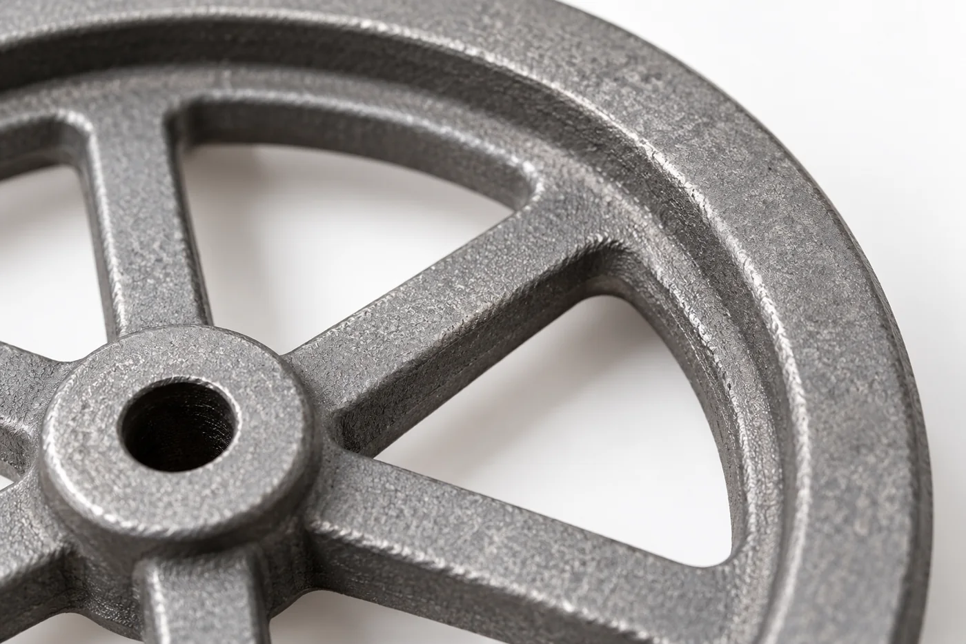
Rim-to-hub transitions remain part of the rotating design
The rim, connecting structure and hub carry the load path of the rotating wheel. Preserve section transitions, fillets and local features in the model. A modification to remove stock or simplify forming may change more than the external appearance.
Show regions open to a manufacturing proposal and those fixed by the design. Retain required stock for the bore and locating faces without losing the accepted sections. The finished casting should follow one approved geometry rather than a combination of a sample shape and unrelated machining assumptions.
- Structure
- Released rim, web and hub geometry
- Machining stock
- Retained at nominated interfaces
05A CLEARER CASTING PURCHASE
Carry the cast structure into the shaft reference
The forming plan has to reproduce the rim, spokes or web and hub without losing the sections fixed by the rotating design. Pattern parting, core needs and the feeding proposal follow those actual transitions. Keep usable machining stock at the bore and locating faces; adding or removing metal at a rim is a design change when it alters the accepted mass distribution.
After casting and preparation, establish the mounting reference, then machine the specified bore, drive feature and locating face in a sequence that preserves their relationship. Relate the required rim and face checks to that running axis. The output is a geometrically defined flywheel with its selected material condition recorded. Any ordered balancing follows its specified final configuration; speed-related engineering evaluation needs its own condition and acceptance rather than being inferred from a balance result.
- 01Form the rotating blankPreserve rim/hub transitions and final stock
- 02Establish mounting datumsBore or other actual shaft connection
- 03Complete related featuresDrive, face and rim relationships
- 04Record the delivered stateMaterial, dimensions and separately ordered rotor checks
06A CLEARER CASTING PURCHASE
Balance, runout and speed qualification answer different questions
Runout is a geometric relationship to the running axis; balancing addresses mass distribution about it. ISO 21940-11 provides a framework for rigid-rotor residual-unbalance and correction-plane requirements where applicable. Specify the rotor configuration, mounting method and permitted correction regions if balancing is ordered.
A balance result is not a universal maximum-speed qualification. Any specified speed-related evaluation needs its own design basis, test object and acceptance. Agree the required evidence for the supplied flywheel rather than allowing the phrase rotating part inspection to conceal several different tasks.
07A CLEARER CASTING PURCHASE
The finished hub keeps its material and surface identity
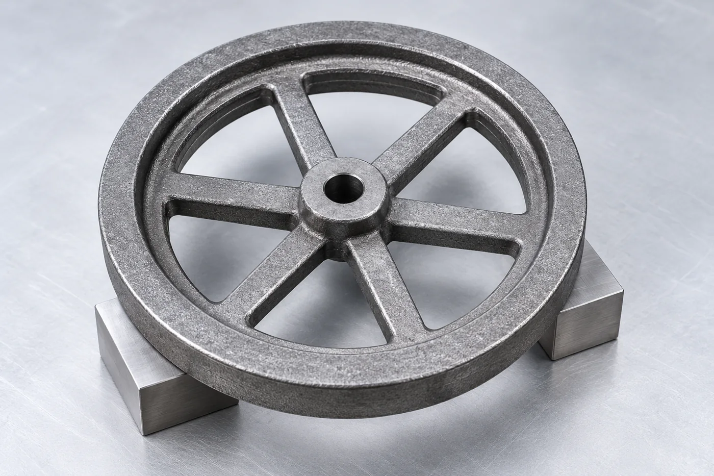
Inspect the drive feature, bore, locating face and required rim relationships against the final drawing. Keep the material condition associated with those results. If the component is balanced, the recorded configuration should match the machining state being delivered.
Specify treatment coverage and protection on the hub and mounting surfaces. A coating or later re-cut at the interface changes the part condition used for assembly. Keep that change visible so an earlier component or balance result is not silently applied to a different rotating configuration.
- Mounting
- Bore, drive feature and locating face
- Separate checks
- Runout, balance and speed evaluation
08A CLEARER CASTING PURCHASE
The sample release records the final configuration
Use the offered sample stage to establish the material, geometry and supplied-surface reference. Record the component identity, drawing revision and required report. Include any defined balancing or other ordered examination in the same release package.
Your machine-assembly evaluation can then use that identified flywheel. If the trial changes a hub, rim feature or attached hardware, assess its effect on the final configuration before repeating the order. This makes a later purchase refer to the component actually accepted rather than an earlier sample that only looked similar.
- 0101Accept the selected iron and complete rotating geometry
- 0202Verify finished shaft and rim relationships
- 0303Record any ordered balance or engineering evaluation
- 0404Freeze the supplied configuration for repeat batches
09A CLEARER CASTING PURCHASE
Support and protection preserve the rotating interfaces
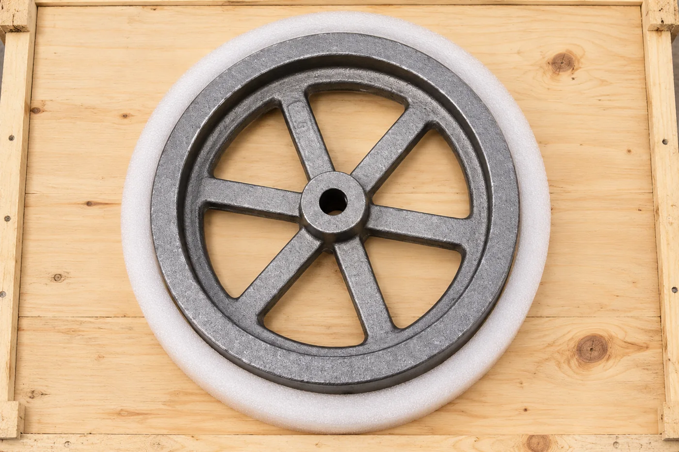
Plan delivery support around the actual flywheel geometry and the handling requirements of your plant. Protect the bore, drive feature, locating faces and vulnerable rim edges from impact and corrosion. Do not use a finished interface as an unintended packing contact.
Keep component identity and orientation clear through receipt. If several flywheels share one shipment, separate their revisions and any configuration-dependent records. Receiving checks can then assess the same shaft and envelope features used for final acceptance before the wheel enters the machine.
- Support
- Actual rim/hub handling geometry
- Protection
- Finished shaft and locating contacts
10A CLEARER CASTING PURCHASE
A flywheel release tied to the machine configuration
Relia can connect the chosen iron casting and nominated machining to a flywheel that your assembly team can identify and inspect. The material record, mounting geometry and any specified balance result should describe that final supplied state.
Use drawing review and the inspected sample to establish the manufacturing reference, followed by your confirmation before batch production. Keep any trial changes to the rim, hub or attached hardware in the accepted design. That gives repeat purchases a reliable component definition while keeping the machine's speed and operating evaluation with its actual assembly conditions.
11 YOUR NEXT STEP
Bring your component into the conversation
Tell us which component you need, the material, quantity and required supplied condition. Relia will connect your enquiry with the casting, machining and evidence relevant to that part.
Technical reading and scope
Technical references explain the process. Component specifications and agreed order records define the actual supply.
Sandia/DOE — flywheel rotational energy principlesISO21940-11 — rigid-rotor balancing- [email protected]
- Phone
- +86 18561762631
- +1 404 203 0971
- Company and address
- Qingdao Relia Industries Co., Ltd.
Shuyuan Road, Qingdao, Shandong, China