
01A CLEARER CASTING PURCHASE
HT350 Bases for Hydraulic Injection Equipment
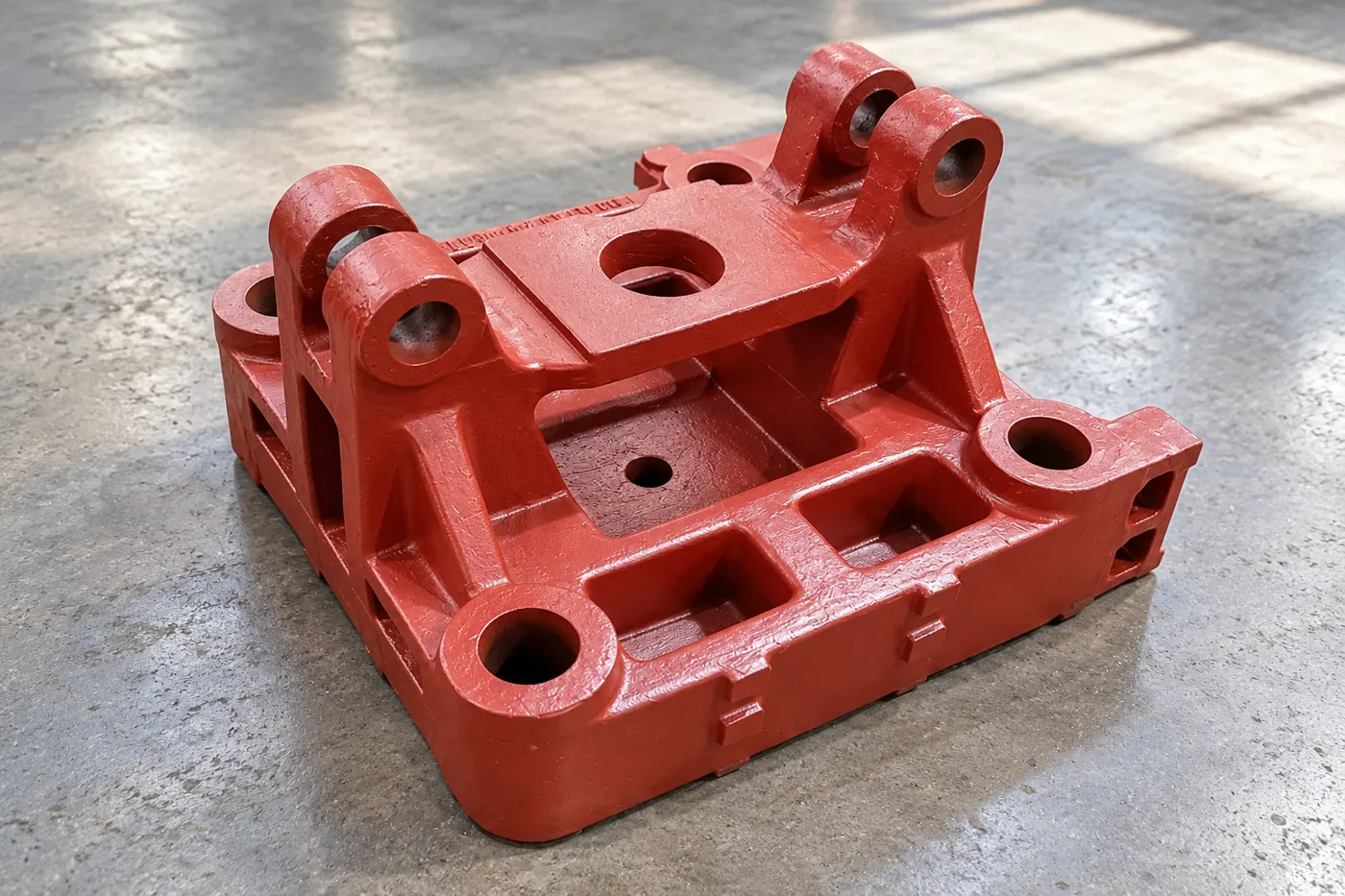
Source the HT350 cast base around the contacts that locate your equipment. Relia’s scope includes tooling, mould manufacture, prototypes and selected machining. Identify support pads, locating features and fastening geometry on the machine layout. The material and dimensional records can then support acceptance of the base in its required installation condition.
- Material
- Selected HT350 requirement
- Interfaces
- Pads, locators + fixings
- Supply
- Cast base + nominated machining
02A CLEARER CASTING PURCHASE
Equipment bases from tooling to nominated CNC interfaces
Relia Casting's HT350 base offer lists in-house tooling design, mould manufacture and prototyping, alongside 3-, 4- and 5-axis CNC milling, turning and EDM service options. Painting and powder coating are available finish enquiries. The selected base drawing decides which of those operations is useful; the list is not one compulsory route.
Our own sand-casting and machining production supports a base whose equipment-contact pads, locating features and fastening geometry share a controlled definition. The catalogue names 100% inspection for the ordered component. Material/dimensional reports and real workshop photographs are available, so your team can assess the part and the production source together.
03A CLEARER CASTING PURCHASE
HT350 specified with its governing material condition
Retain HT350 with the complete material standard, delivered condition and required evidence. A grade name should stay connected to the sections and service design for this iron base. The wider listing's aluminum, stainless, brass and copper enquiries are separate components, not substitutions for the HT350 order.
State the material checks needed for release and the identity of the casting or batch to which they apply. Where treatment is specified for dimensional stability or material condition, put its sequence and required record in the base's manufacturing package.
| Material decision | Order definition |
|---|---|
| Material | HT350 with full governing specification |
| Condition | Selected treatment/state for the actual base |
| Evidence | Required material result and casting/batch identity |
| Drawing basis | Sections, interfaces and controlled revision |
04A CLEARER CASTING PURCHASE
Contact pads need a usable area and a datum relationship
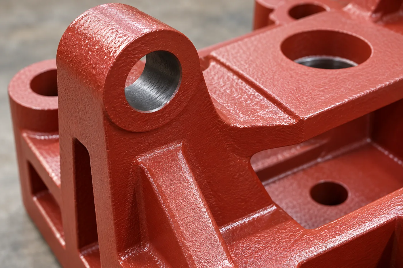
A mounting pad must have the required contact area, position and geometry for its mating component. Identify interruptions, nearby ribs and fastener seating regions. The local finish does not describe how that pad relates to the other equipment supports.
Dimension pad heights, plane relationships and locating features from the selected datums. Retain machining stock without reducing the designed section under the pad. This connects the cast supporting geometry to the final installation instead of treating every exposed surface as equally precise.
- Contact pad
- Usable area and supported local section
- Location
- Pad height and relation to other supports
05A CLEARER CASTING PURCHASE
Create the support geometry before accepting the finished pads
The base tooling has to carry the actual ribs, walls and mounting bosses into a blank with stock at the future pads. Pattern parting, core location where needed and the feeding proposal should address the junctions beneath those load-transfer regions. Local stock is useful only if the finished pad can be reached without reducing the required section.
After casting and preparation, establish the base references and complete the relevant rough work. Material removal can redistribute stress, so any specified treatment or intermediate recheck belongs in the plan before final pad and locating-feature acceptance. Choose milling, boring, turning or EDM only where the design needs it. The output is a base whose final contact map is measured from the equipment datums, with the supplied material state and surface boundaries recorded.
- 01Tooling and blankRibs, pads, parting and stock beneath contacts
- 02Rough/reference workStable datums and planned stock removal
- 03Specified intermediate stageTreatment or recheck where required by the base plan
- 04Finish and measureContact-pad relationships and locating/fastening features
06A CLEARER CASTING PURCHASE
Component geometry and installed-machine behaviour checked separately
The base report should state whether the material and finished interfaces meet the drawing. It should identify the measurement setup, pad relationships and locating features used for that decision. Our scope includes 100% inspection under an ISO9001-system reference for the ordered component.
Installed equipment then needs its own alignment and operating evaluation. ISO 230-1 illustrates the distinction between geometric machine testing under no-load/quasi-static conditions and operational behaviour. Select the actual equipment test plan rather than turn a component dimension report into a claim about the machine cycle.
07A CLEARER CASTING PURCHASE
The mating part determines local finishing requirements
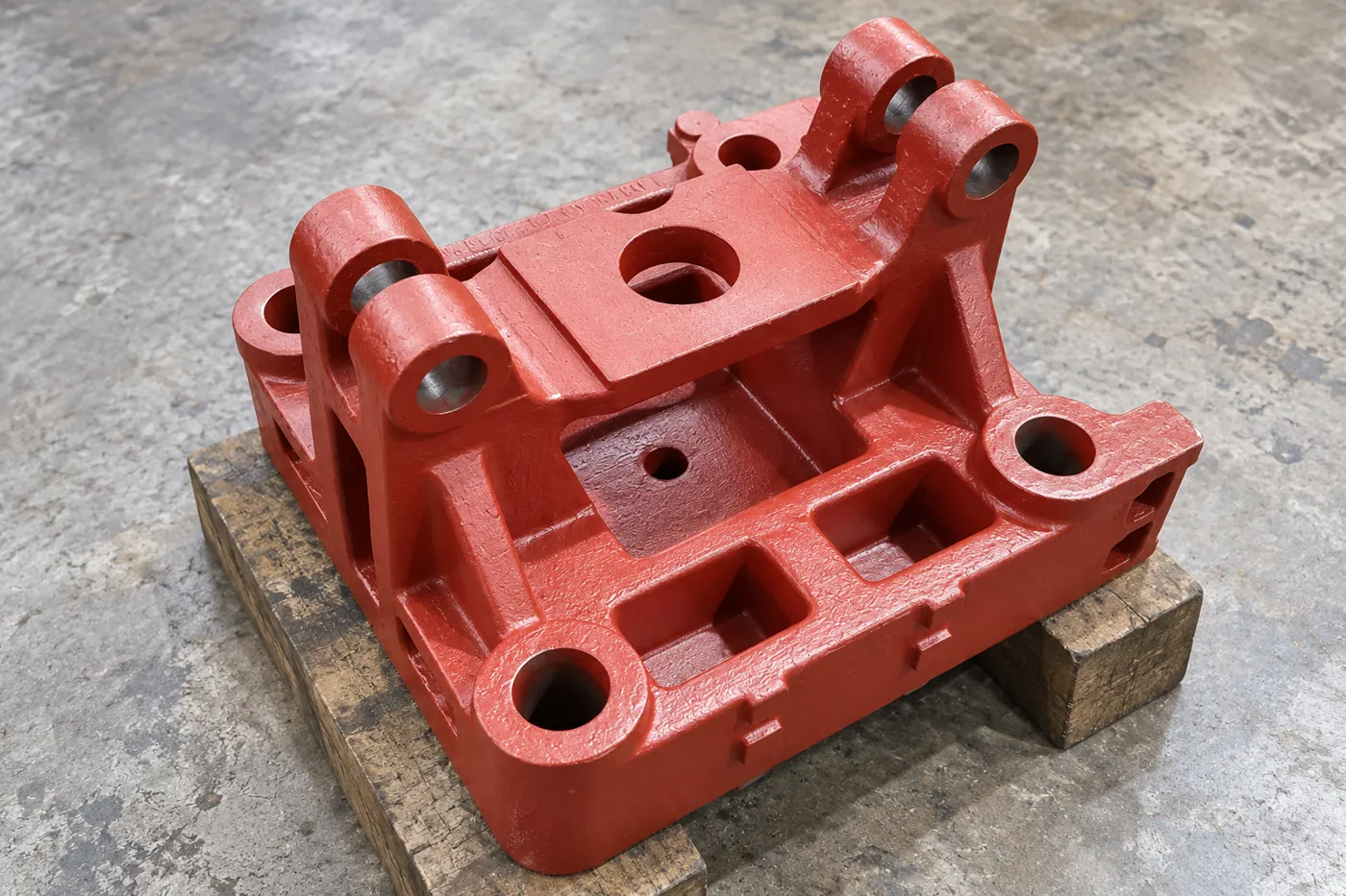
Mark the final surfaces used first by the equipment assembler, including pad lands, locating bores and thread details. Give each feature its own limit. The catalogue's 0.01–0.05 mm reference is allocated to agreed finished dimensions; it is not a flatness or position guarantee for every surface of a large base.
Painting and powder coating are available finish enquiries. Define masking and final contact condition around the machined features so coating does not change the support or location that the finished drawing establishes.
- Finished feature
- 0.01–0.05mm reference on agreed dimensions
- Surface
- Paint/powder masking at machine interfaces
08A CLEARER CASTING PURCHASE
The prototype closes the installation questions early
Use tooling or prototype work where the design needs an early check of clearance, access or pad arrangement. Record what the sample demonstrates and which dimensional or material results are required. A geometry prototype and a production-material casting can answer different questions.
For the first supplied base, compare the actual interface report with a controlled installation trial. Keep any local adjustment in the engineering record. The approved base revision and mating-equipment reference should then form the repeat-order definition rather than an undocumented sample fit.
- 0101Identify prototype purpose and production material requirements
- 0202Measure related pads, locating features and fastening geometry
- 0303Record installation clearance and alignment observations
- 0404Freeze compatible base and mating-equipment revisions
09A CLEARER CASTING PURCHASE
The support and coating condition preserved in delivery
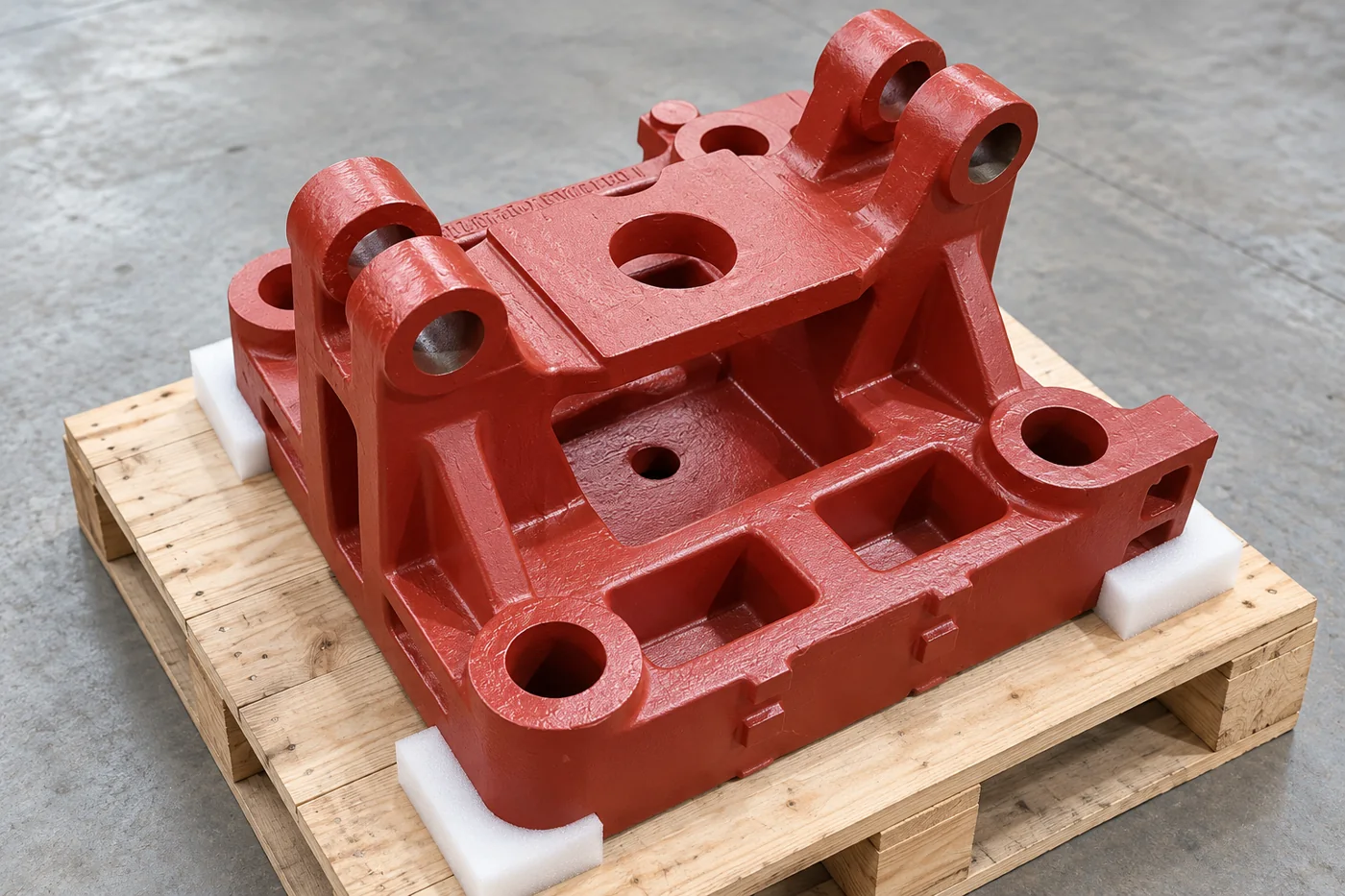
Specify how the base is supported in transit and during receipt, with protection for finished pads and locating features. Avoid using a machined land as an unplanned packing or handling contact. Retain the required coating and clean surface condition at assembly interfaces.
Keep temporary protection distinguishable from final paint and identify anything the receiving team must remove. Connect the base identity to its drawing, material and feature report. This lets your team accept the delivered component before placing the hydraulic equipment on it.
- Protection
- Finished pads and locating areas
- Receiving
- Material and feature report linked to base identity
10A CLEARER CASTING PURCHASE
An installation base with a repeatable interface record
The useful base purchase links the selected HT350 condition, cast structure, completed contacts and measurement setup. Relia can manufacture that sand-cast and machined package, with tooling/prototype scope available where the design needs an early installation check. Drawing review, sample manufacture and inspection, then your confirmation provide the basis for batch production.
Keep the accepted pad map, locating arrangement and mating-equipment revision with repeat orders. A component report demonstrates the supplied base geometry; the installed hydraulic equipment follows its own alignment and operating evaluation. This gives your machine team an identifiable foundation for the next assembly stage.
11 YOUR NEXT STEP
Bring your component into the conversation
Tell us which component you need, the material, quantity and required supplied condition. Relia will connect your enquiry with the casting, machining and evidence relevant to that part.
Technical reading and scope
Technical references explain the process. Component specifications and agreed order records define the actual supply.
Casting stress redistribution during machiningISO 230-1 — geometric machine testing scope- [email protected]
- Phone
- +86 18561762631
- +1 404 203 0971
- Company and address
- Qingdao Relia Industries Co., Ltd.
Shuyuan Road, Qingdao, Shandong, China