
01A CLEARER CASTING PURCHASE
Large Thin-Wall Aluminum Housings
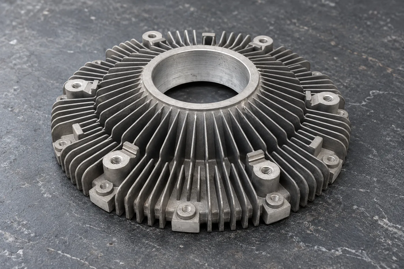
A thin-wall housing needs a usable shape after it leaves the fixture. Relia’s aluminum machinery range supports selected sand, gravity and die-casting proposals with design and machining enquiries. Show the wall spans, ribs, flanges and finished interfaces together. Use the prototype to assess the actual support and processing plan, including whether final dimensions are accepted free or under a defined restraint.
- Define
- Wall spans + interfaces
- Plan
- Support + processing sequence
- Accept
- Free or specified restrained state
02A CLEARER CASTING PURCHASE
Describe thinness through thickness and unsupported span
Relia’s aluminum housing scope is selected against the actual drawing and delivered condition. Our own casting and machining production provides a basis for the route discussion, while the specific sand, gravity or die-casting option must remain explicit in the quotation.
A wall’s behaviour depends on its local thickness, span and connection to ribs or flanges. Mark these features on the model, including openings and any region unavailable for support. The overall envelope helps plan access, but a small unsupported panel can drive a machining problem inside a much larger housing. Identify the surfaces that establish assembly and the regions where a manufacturing adjustment is permitted. This turns a broad thin-wall enquiry into a geometric problem with identifiable decisions.
03A CLEARER CASTING PURCHASE
Select the route around the actual housing geometry
Our aluminum machinery offer includes sand, gravity and die-casting directions, with 2D and IGS/STP design input. Compare the relevant route using the alloy, internal geometry, wall distribution and expected quantities. The large one-off range lists wood and aluminum patterns, with a CT7–CT10 casting reference for its selected blank scope. These are starting options, not a single prescribed sequence. The route proposal should identify the geometry it can produce and the local stock and access required to reach the finished part.
- 01Define geometryRelease walls, ribs, openings and fixed assembly interfaces.
- 02Choose materialSet the alloy and required supplied condition.
- 03Compare routeAssess the relevant casting/tooling arrangement.
- 04Plan machiningDefine stock, supports and the final checking state.
- 05Release trialTest the selected proposal against specific acceptance characteristics.
04A CLEARER CASTING PURCHASE
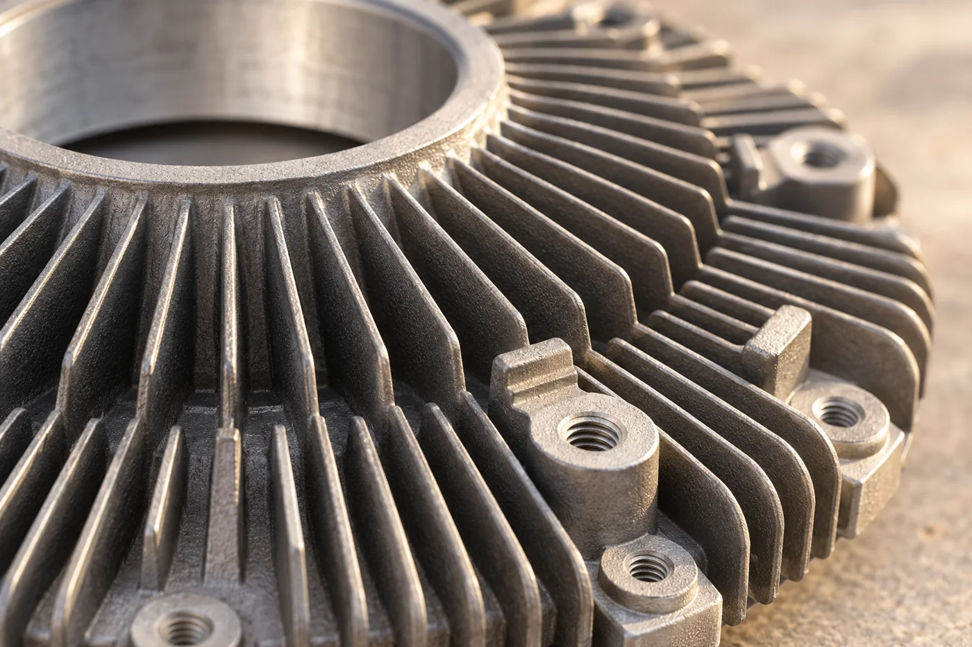
Keep ribs and mounting features in the same stiffness model
A rib near the mounting rim can provide useful support, while a long fin or thin edge may be unsuitable for clamping. Review the complete geometry before choosing contact points. If an added pad or temporary support feature is proposed, identify how it will be removed and which surfaces it can influence. The design change should remain connected to the final model, so the machining plan does not improve one local operation by creating a new installation or surface problem elsewhere on the housing.
05A CLEARER CASTING PURCHASE
Support the cut without forcing the acceptance shape
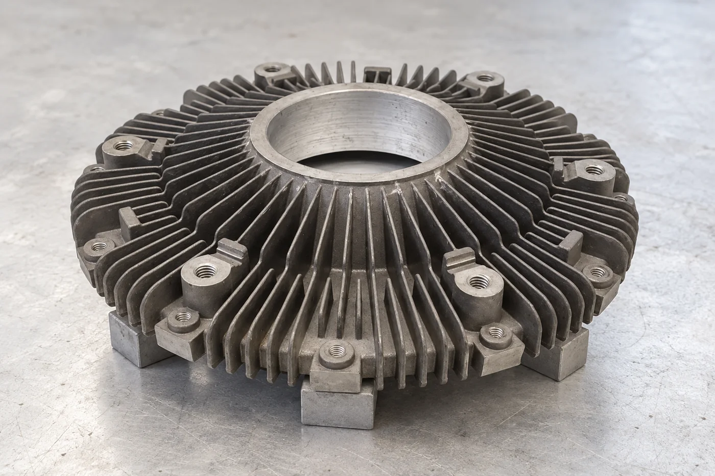
Choose support locations near robust regions and the area being machined, while retaining access and protecting finished surfaces. Original machining guidance highlights tool/fixture stability and avoiding cutting into poorly supported directions. For your housing, the proposal should also address clamping force: forcing a flexible rim flat during machining can mask the shape that returns after release. Define the locating and support arrangement, how the wall is restrained and the condition used for final acceptance.
| Fixturing decision | Practical purpose |
|---|---|
| Support location | Carry cutting loads through suitable geometry near the operation. |
| Clamping region | Avoid relying on a flexible fin or forcing the wrong shape. |
| Tool access | Keep the required path clear with a stable tool/fixture arrangement. |
| Release check | Assess the nominated feature after the required restraint is removed or applied. |
06A CLEARER CASTING PURCHASE
Coordinate material state and rough-to-finish work
If the selected alloy requires treatment, include it in the dimensional plan rather than add it after the final interface has already been accepted. Solution-treatment and quench operations can change geometry and introduce residual-stress considerations. For the actual casting, agree the appropriate sequence and any intermediate assessment. Roughing, re-establishing support and final finishing may have different roles. The purpose is to retain enough useful stock and a credible datum chain through the operations chosen for this housing, with the final measurement made in the condition your assembly requires.
07A CLEARER CASTING PURCHASE
State the restraint condition beside shape acceptance
A free housing, a lightly supported housing and one bolted into an assembly can show different shape readings. Define which state the flatness or other requirement applies to, with the support positions and restraint details needed to reproduce it. Do not let a measurement fixture quietly become the assembly condition. Our aluminum offer’s ±0.02 mm reference needs a nominated feature and state; final housing shape should be accepted against its own drawing requirements rather than that value applied indiscriminately to the entire casting.
08A CLEARER CASTING PURCHASE
Use the trial to expose the critical geometry change
Choose sample checks that show the effect your team is concerned about. For example, compare a defined rim or face in the specified support state after relevant processing stages, then inspect the final required condition. Record the feature, setup and result so a change in clamping or sequence can be evaluated meaningfully. The trial should support a decision about the actual route and fixturing proposal, with a revision or repeat release based on identified geometry rather than a broad visual judgement.
- 0101Release the wall/span map, material condition and final acceptance state.
- 0202Define the proposed supports, clamping regions and processing sequence.
- 0303Measure the selected shape characteristics at the planned stages.
- 0404Resolve the affected geometry/process choice before repeat release.
09A CLEARER CASTING PURCHASE
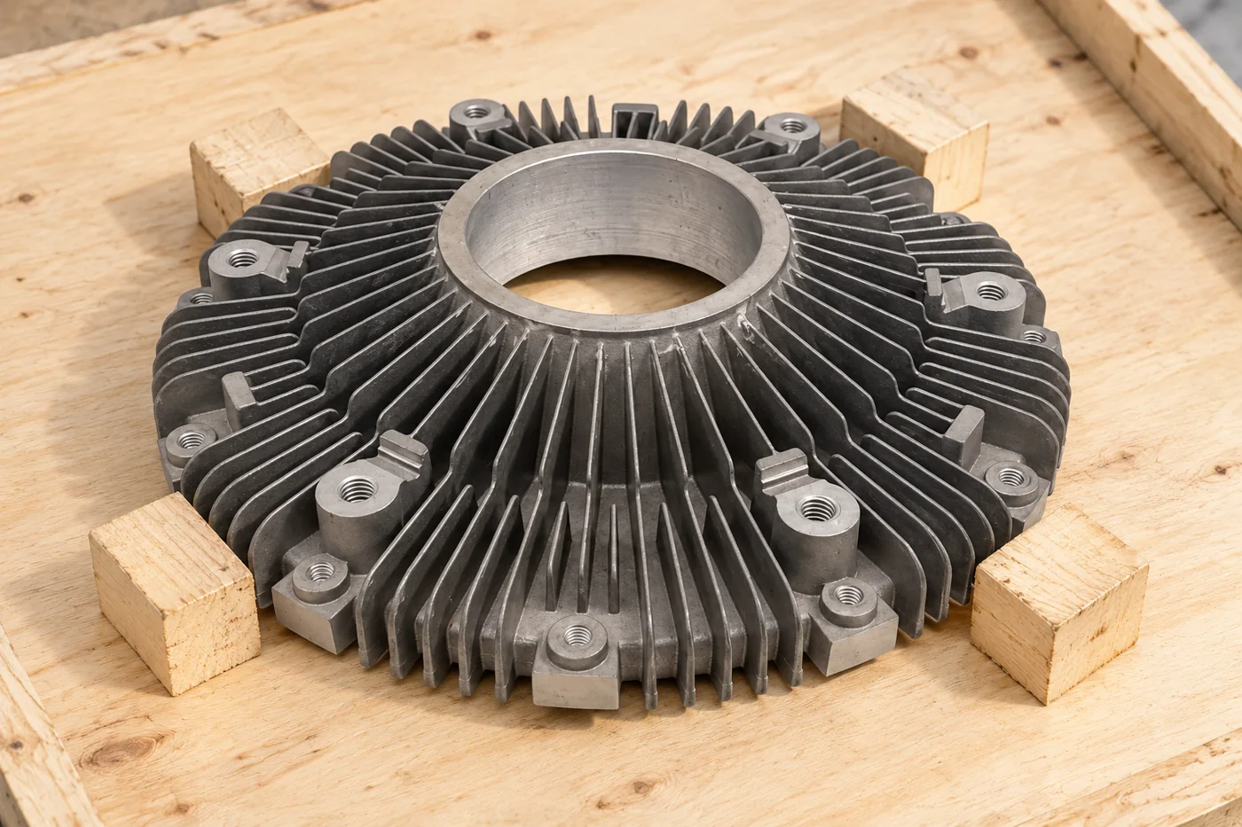
Keep packing loads away from flexible regions
The transport support arrangement should preserve the shape and interfaces accepted during the trial. Support through robust areas, separate components and prevent straps or blocks from loading a flexible fin, lip or unsupported panel. Identify the final mounting surfaces that need protection and the sequence your team will use when unpacking and checking the housing. The delivered-condition brief then remains consistent with the fixturing and measurement decisions made during development rather than introducing a different restraint during transit.
10A CLEARER CASTING PURCHASE
Request a thin-wall proposal with a measurable outcome
Send the complete model and drawing with the alloy, local thicknesses, spans and finished interfaces. Add the condition in which shape must be accepted and the sample quantities. We can then assess the casting, support and machining proposal around the real housing. Your purchasing comparison can focus on the proposed handling of the difficult regions, the sequence used to reach the final state and the trial evidence that supports a repeat-order decision.
11 YOUR NEXT STEP
Bring your component into the conversation
Tell us which component you need, the material, quantity and required supplied condition. Relia will connect your enquiry with the casting, machining and evidence relevant to that part.
Technical reading and scope
Technical references explain the process. Component specifications and agreed order records define the actual supply.
Milling Vibration and Workpiece Support — Original Tooling GuidanceAluminum Heat-Treatment Process Considerations — NASA JSC- [email protected]
- Phone
- +86 18561762631
- +1 404 203 0971
- Company and address
- Qingdao Relia Industries Co., Ltd.
Shuyuan Road, Qingdao, Shandong, China