
01A CLEARER CASTING PURCHASE
Printed Sand Cores for Complex Prototypes
Choose the deliverable your next team needs: a printed core, a matched mould-and-core set, or a finished metal prototype. Relia’s catalogue includes binder-jetted silica-sand cores with resin binder, alongside manifold and engine-prototype enquiries with casting and CNC work. Use printed sand where internal geometry or continuing revisions justify it, while defining the dimensions, handling and evidence for the actual object ordered.
- Deliverable
- Core, mould or metal part
- Purpose
- Complex internal geometry
- Compare
- Printed + conventional scope
02A CLEARER CASTING PURCHASE
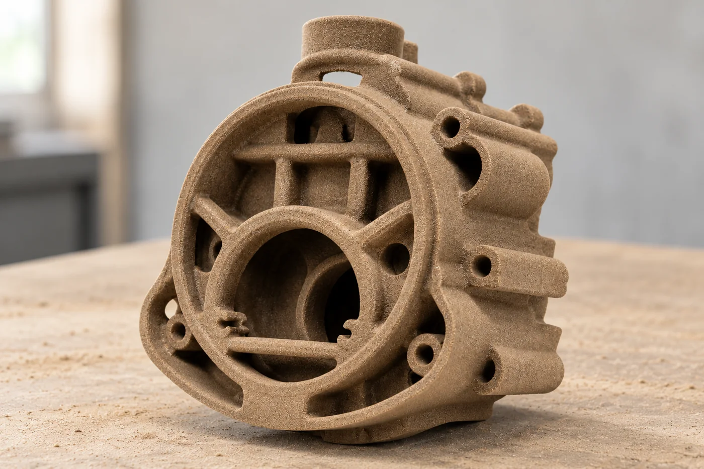
Choose the object that your next operation needs
Relia’s printed-sand offering and metal-component development are distinct supply stages. Our own casting and machining production can be discussed alongside the selected printed-sand handover, without assuming that every enquiry includes a finished metal component.
A printed core defines a cavity inside the casting; a mold defines the surrounding forming space. Neither is a metal component ready for a functional test. Our printed-sand offering is supplied as printed, with a one-piece minimum for the defined sand object. The manifold and engine-prototype ranges add separate casting and machining possibilities. Specify which handover you need so the quotation includes the operations that turn the digital geometry into the object your next team can actually use.
03A CLEARER CASTING PURCHASE
Design passage geometry with location and removal in mind
A curved internal passage can benefit from a printed core, but the core still has to locate and survive the chosen casting sequence. Show core seating, slender branches and any region whose movement changes wall thickness. Also show how the sand will be removed from the finished cavity. SFSA identifies cleaning access as a casting-design consideration. For your prototype, passage feasibility therefore includes both making the cavity and reaching a clean metal component suitable for its intended inspection or test.
| Model feature | Manufacturing decision |
|---|---|
| Core seating | Locate the sand object relative to the external mold. |
| Slender branch | Provide a handling and support approach for the selected geometry. |
| Passage outlet | Retain access for cleaning and any required internal inspection. |
| Critical wall | Relate core position to the surrounding metal envelope. |
04A CLEARER CASTING PURCHASE
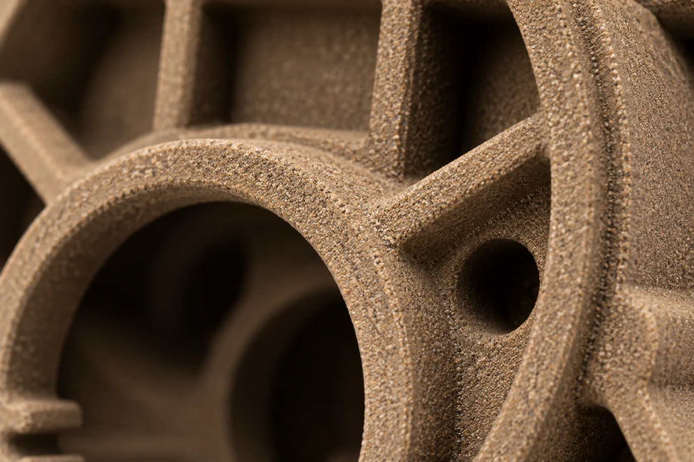
Apply printed-sand accuracy to the sand object
Our BJ core listing states silica sand with resin binder, an as-printed tan/brown condition and a ±0.3 mm dimensional reference. Locate that requirement on the nominated core or mold features and define how it is checked. The finished metal adds its own casting and machining stages, so the same number is not a finished-component tolerance. Likewise, the listed 200 × 150 × 120 mm example describes an example object; it is not the maximum printing envelope for every enquiry.
05A CLEARER CASTING PURCHASE
Compare a printed core with a complete printed mold
Printed cores can be combined with a conventional mold, while a more extensive printed set may be appropriate when the external geometry is also changing. Original process guidance describes this hybrid use of printed sand. For your project, compare which geometry needs digital flexibility and which forming equipment already exists. A complex passage alone does not always require printing the complete mold. Choose the route around the revisions you expect and the handover that the selected metal-casting process needs.
- 01Component modelRelease the passage and external geometry together.
- 02Core/mold selectionPrint only the objects needed by the proposed forming arrangement.
- 03PreparationSpecify support, cleaning and any agreed surface preparation.
- 04Metal castingUse the selected alloy and component-specific casting route.
- 05FinishingMachine and inspect the interfaces needed by the prototype test.
06A CLEARER CASTING PURCHASE
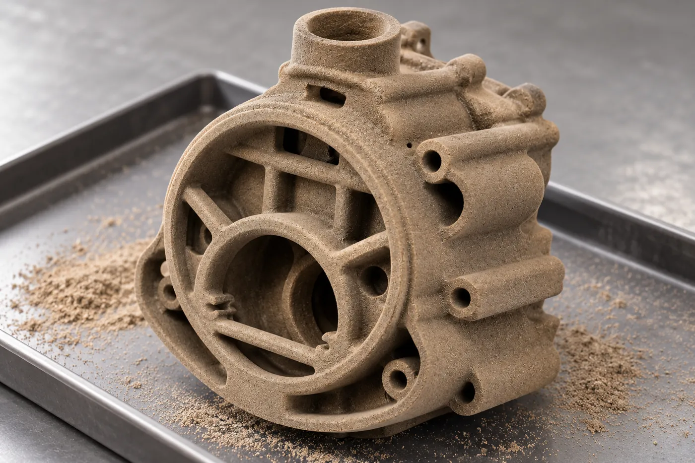
Support the core through preparation and assembly
A large opening can make a sand object easy to recognize while leaving a thin rib vulnerable during handling. Identify the robust surfaces used to support and move it, and keep fragile branches clear of packing loads. Preparation also needs to leave the locating seats usable so the core enters the mold in the intended position. Discuss any coating or other preparation required by the chosen casting arrangement as a defined operation, rather than assume that as-printed delivery includes every foundry preparation step.
07A CLEARER CASTING PURCHASE
Measure the stage that answers the prototype decision
Core checks establish the supplied sand geometry; metal checks establish the actual cast and machined part. For a passage prototype, select the characteristics that matter to the development decision, such as a defined wall region, connection position or accessible internal section. The manifold offer includes strict 100% inspection and a range of CNC operations, so connect that coverage to named features and records. Add an application test separately when the prototype needs to demonstrate flow, pressure or another working result.
| Evidence stage | Decision supported |
|---|---|
| Printed object | Specified seat, envelope and passage-form dimensions. |
| Cast metal | Material and the required internal/external geometry. |
| Finished interfaces | Bores, faces, threads and drawing-referenced dimensions. |
| Functional trial | The defined buyer test and its operating acceptance. |
08A CLEARER CASTING PURCHASE
Revise the geometry that caused the finding
A prototype finding may concern the passage design, the core location or the machining interface. Keep those causes separate before changing the model. If the flow path changes, update the core and component references together; if the issue is location, preserve the intended passage while revising its seating arrangement. This is where printed geometry can make iteration useful, but the next build still needs a controlled revision. Record which differences are being tested so a successful result belongs to the design actually supplied.
- 0101Connect the finding to a passage, seat, wall or finished feature.
- 0202Identify whether geometry or the manufacturing arrangement needs to change.
- 0303Release aligned component and sand-object revisions.
- 0404Repeat the affected checks before progressing the prototype.
09A CLEARER CASTING PURCHASE
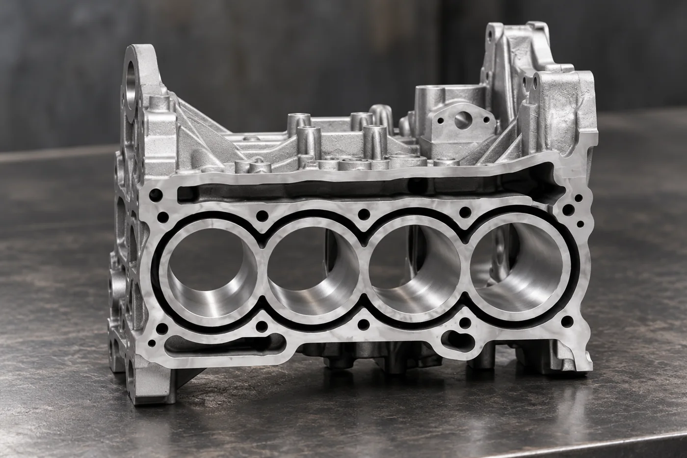
Specify the metal prototype as a finished engineering object
Our engine-block and cylinder prototype scope includes printed sand molds, metal or low-pressure-casting requests and CNC machining. Select a compatible route rather than treat all named methods as one compulsory sequence. A metal prototype needs its alloy, bore and mounting requirements defined independently from the printed sand. For an evaluation focused on a particular internal region, retain that region and its connections in the supplied definition so the resulting trial answers the intended engineering decision.
10A CLEARER CASTING PURCHASE
Send a prototype package that follows the cavity
Provide the controlled component model and drawings, the selected alloy and the internal regions that make conventional tooling difficult. Add the sand-object or finished-metal deliverable, quantity and prototype purpose. We can then discuss a core/mold arrangement, preparation and finishing scope that connect to that purpose. Your purchasing decision becomes a choice of manufacturing route with explicit geometry and evidence, rather than a request for an intricate printed shape alone.
11 YOUR NEXT STEP
Bring your component into the conversation
Tell us which component you need, the material, quantity and required supplied condition. Relia will connect your enquiry with the casting, machining and evidence relevant to that part.
Technical reading and scope
Technical references explain the process. Component specifications and agreed order records define the actual supply.
Printed Sand Cores and Molds — Original Process GuidanceOrdering Steel Castings — SFSA- [email protected]
- Phone
- +86 18561762631
- +1 404 203 0971
- Company and address
- Qingdao Relia Industries Co., Ltd.
Shuyuan Road, Qingdao, Shandong, China