
01A CLEARER CASTING PURCHASE
GGG50 Semi-Open Pump Impellers
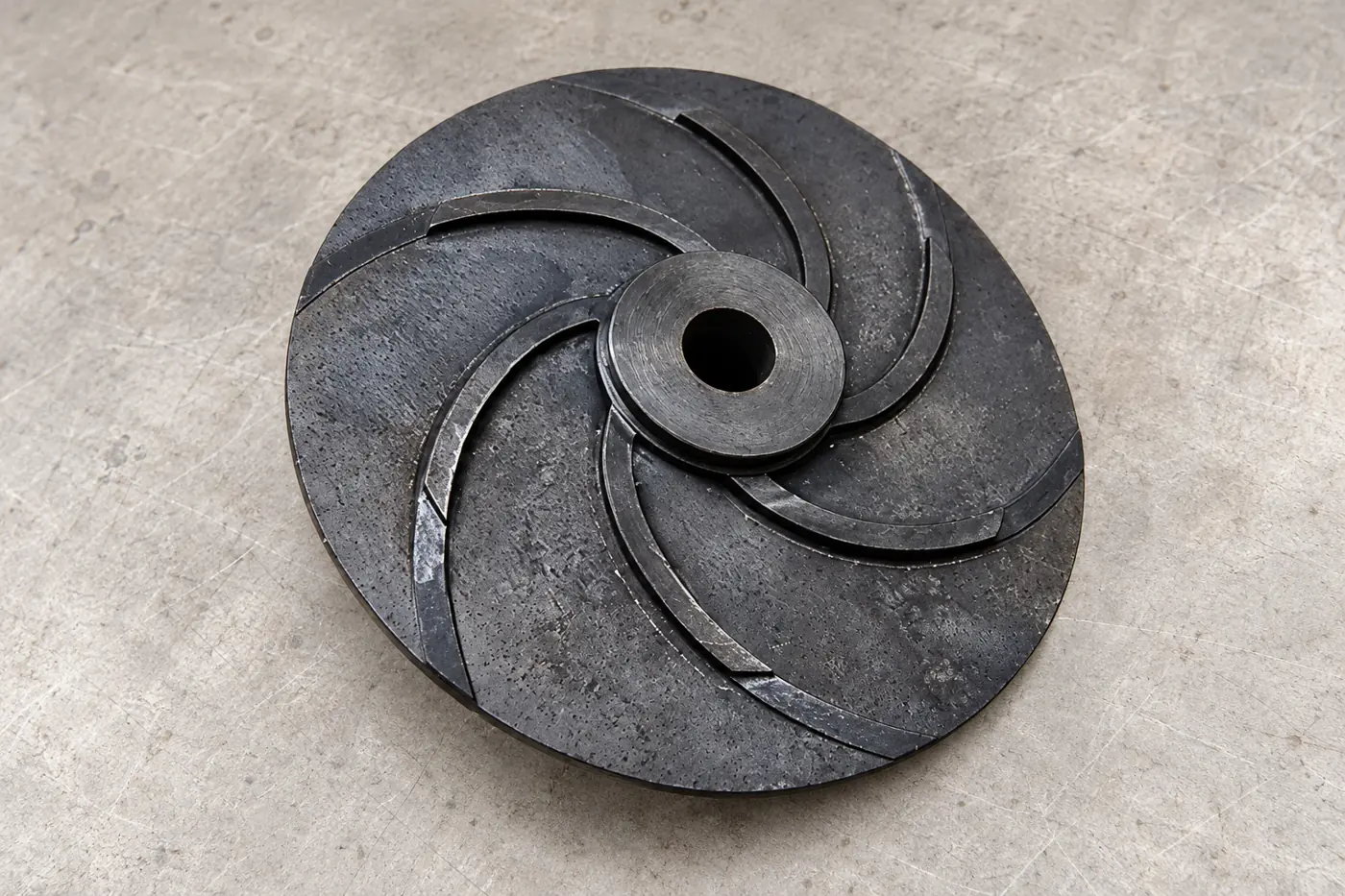
Relia supplies GGG50 ductile-iron semi-open impellers through shell-mould casting and CNC finishing. Source the vane body and shaft connection as one component, with the bore, locating face and working clearances defined together. Our own casting and machining production supports the drawing-based route, followed by sample inspection and your approval before batch production.
- Material
- GGG50 ductile iron
- Route
- Shell mould + CNC
- Fit
- Bore + locating face
02A CLEARER CASTING PURCHASE
Vane bodies and shaft interfaces from one production source
Relia Casting supplies GGG50 semi-open impellers and related pump parts with shell-mould casting and CNC finishing. Our factory has its own sand-casting and machining production, with coated-sand/shell moulding as its main route. This combination suits OEM teams keeping the hydraulic design while buying a finished rotor interface.
PDF, IGS or STP data can define the vane form, hub and shaft connection. Sandblasting, spray painting, powder coating or a custom treatment can be selected by region. Dimensional and material reports, together with real workshop/equipment photographs, are available to support your component and source assessment.
03A CLEARER CASTING PURCHASE
Vane geometry and material retained as one rotor definition
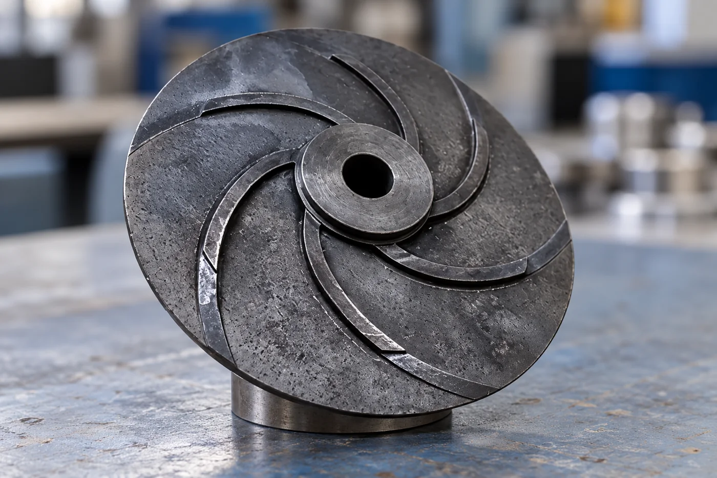
The semi-open design exposes one side of the vane system to the stationary pump surface. Vane height, handedness, inlet shape and diameter therefore belong beside the clearance-setting arrangement. Excess clearance can permit unwanted internal recirculation; insufficient room can cause contact as the assembly moves or heats.
Relia's offering uses GGG50 SG ductile iron and a CT7–CT10 casting reference. That cast-form control is separate from the finished shaft bore and locating-face limits. Keep the complete material condition, vane model and finished interfaces under one revision, so an impeller that fits the shaft also retains the hydraulic form your pump needs.
| Specified layer | Manufacturing decision |
|---|---|
| Hydraulic form | Vane count, handedness, height and inlet/outlet geometry |
| Material | GGG50 governing specification and supplied condition |
| Cast control | CT7–CT10 reference assigned to indicated casting dimensions |
| Finished connection | Separate bore, face and retention acceptance |
04A CLEARER CASTING PURCHASE
The cast vane and machined hub need a shared axis
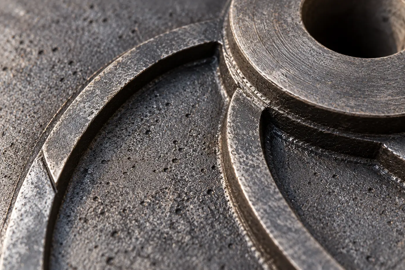
The central bore defines how the impeller runs on the shaft; the vane envelope needs the correct relationship to that axis. Mark the locating face, bore and relevant runout or orientation requirement on the drawing. Otherwise a good bore measurement can coexist with a vane form running eccentrically.
Retain enough machining stock on the hub to reach the finished size without cutting into an unacceptable section. The casting-to-machining plan should preserve the hydraulic geometry while producing the shaft connection that your assembly actually uses.
- Running datum
- Central bore axis
- Cast form
- Vane envelope and hub relationship
05A CLEARER CASTING PURCHASE
Shell moulding and CNC finishing keep the vane and hub related
Shell moulding forms the vane body and hub using a resin-sand moulding system. Pattern and parting choices must release the curved vane form while preserving the hub position. The shell assembly needs adequate integrity and location; a shifted mould can move the available stock before machining starts. Those are route-review and sample-check points, rather than reasons to assume a close bore from a casting class.
After the impeller is cast, gate removal and cleaning leave access to the vanes and hub. The CNC sequence establishes the running bore and locating face, then completes the specified drive or retention features. Check these from the same axis basis used for assembly. The useful output is a cleaned cast vane envelope related to a measured shaft connection, with sufficient stock retained until the finished references are established.
- 01Form the vane bodySelect parting and mould location around the actual curved geometry
- 02Prepare the castingRemove gates and residue without damaging working vane edges
- 03Finish the running connectionCreate bore, locating face and nominated drive details
- 04Measure the relationshipRelate cast envelope and finished features to the running axis
06A CLEARER CASTING PURCHASE
Balancing specified after the final rotating condition
Balancing addresses mass distribution around the running axis; dimensional runout addresses geometry. Both may matter, but they answer different questions. Where rigid-rotor balancing applies, ISO 21940-11 provides a framework for residual-unbalance limits and correction planes. Choose the requirement for your actual rotor and duty.
The balancing brief should state the final component condition, operating speed, mounting method and treatment of keys or retained hardware. Record permitted correction locations so material is not removed from a functional vane or an insufficiently thick region.
07A CLEARER CASTING PURCHASE
The sample connects the finished rotor to its pump setting
Relia's new-part route moves from drawing review to sample manufacture and inspection, then your confirmation before batch production. For an impeller, the sample evidence should identify the bore, locating face and vane envelope together. Any ordered balancing record needs to describe that same final rotor configuration.
Your installation check then sets the intended clearance and retention in the actual pump. A dimensional report helps explain that setting; the separate pump trial establishes hydraulic performance at its defined duty. This division gives an OEM a useful component approval without confusing an accurately measured impeller with a tested complete pump.
- Sample output
- Finished connection and vane feature report
- Buyer check
- Pump clearance and retention setting
08A CLEARER CASTING PURCHASE
A repeat order preserves the approved hydraulic version
A small impeller revision can change more than appearance. Changing the outer diameter, vane height, bore location or correction region may affect the installation or performance basis. Keep these features and the selected finish in the approved production definition.
For repeat supply, distinguish a dimensional concession on one part from an approved design revision. If you change the mating casing, shaft or clearance-setting method, include that change in the impeller review. This prevents an unchanged part number from silently carrying incompatible assembly expectations.
- 0101Freeze vane model, impeller diameter and locating geometry
- 0202Retain material condition and final surface specification
- 0303Keep balancing configuration and correction limits with the order
- 0404Reassess changed casing, shaft or clearance references
09A CLEARER CASTING PURCHASE
Surface treatment and packing protect functional geometry
Sandblasting, spray painting, powder coating and custom treatments are offered. Allocate treatment by surface: a coated bore or locating face can change fit, and buildup on a clearance-sensitive face changes the supplied geometry. Show masking and final-condition requirements on those regions.
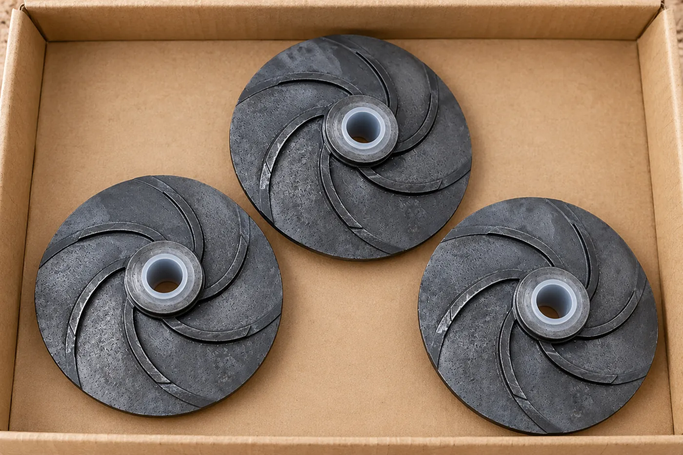
Separate impellers so vane edges cannot strike one another during transit. Protect finished bores and locating faces, identify the approved revision and retain batch identity. The receiving check should find the same geometry and finish that were accepted on the sample.
- Surface
- Mask bore and clearance-sensitive regions
- Packing
- Separate vane edges and finished faces
10A CLEARER CASTING PURCHASE
A finished impeller definition ready for repeat supply
A repeatable impeller order joins the released vane design, GGG50 requirement, CNC shaft connection and final surface state. Relia can supply the shell-mould casting and finishing work around that complete component. The practical comparison is the rotor ready for your next assembly operation, including the specific inspection and any balancing scope you need.
Start with the vane model and bore/retention drawing, quantity and pump duty. We can discuss the sample, the surfaces left as cast and the features finished for installation. Keep the approved geometry and configuration with later releases so a repeat part number carries the same hydraulic and mechanical meaning.
11 YOUR NEXT STEP
Bring your component into the conversation
Tell us which component you need, the material, quantity and required supplied condition. Relia will connect your enquiry with the casting, machining and evidence relevant to that part.
Technical reading and scope
Technical references explain the process. Component specifications and agreed order records define the actual supply.
Internal clearance flow and leakage lossISO 21940-11 — rigid-rotor balancingShell moulding and mould-shift considerations — ASM abstract- [email protected]
- Phone
- +86 18561762631
- +1 404 203 0971
- Company and address
- Qingdao Relia Industries Co., Ltd.
Shuyuan Road, Qingdao, Shandong, China