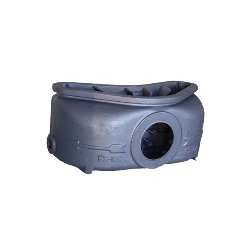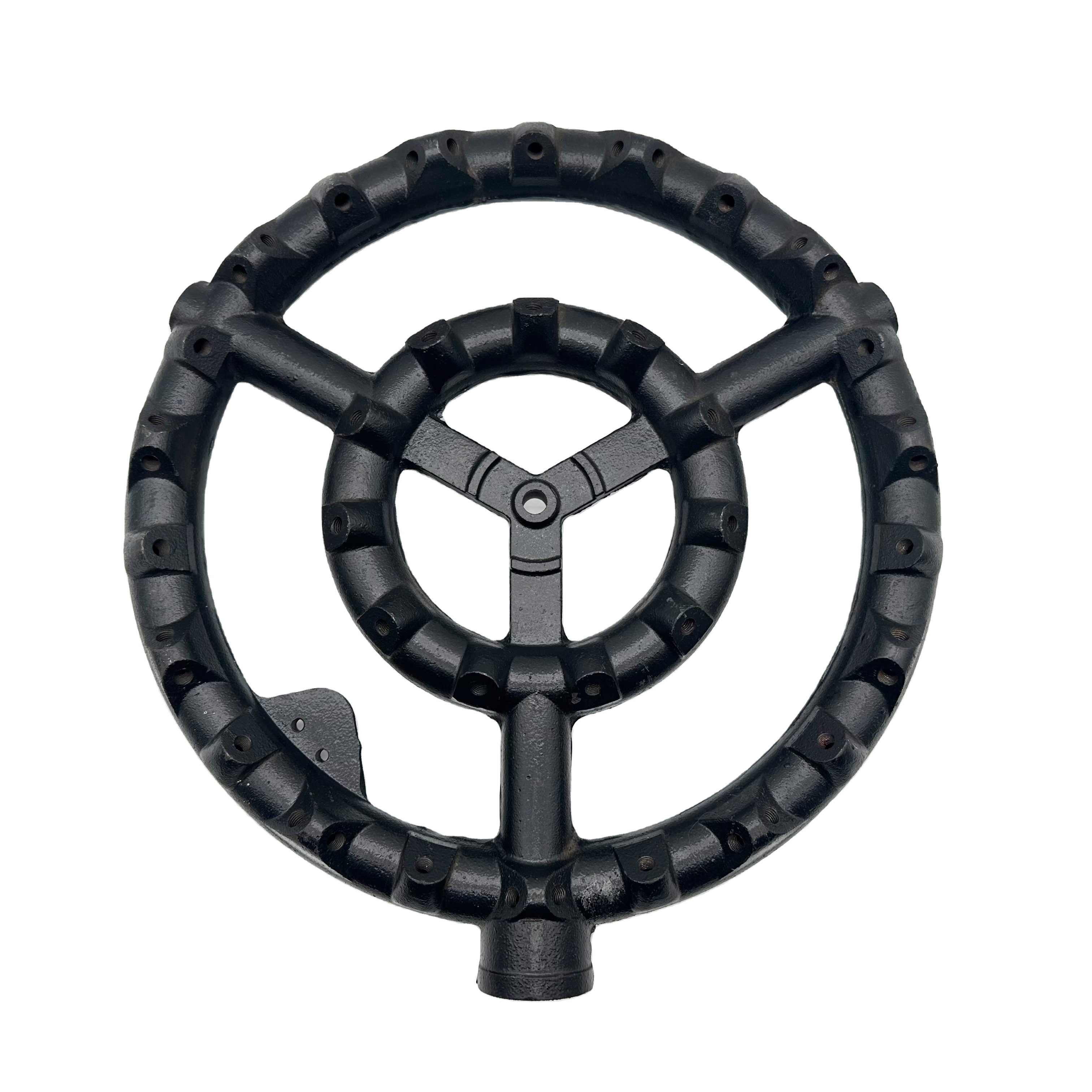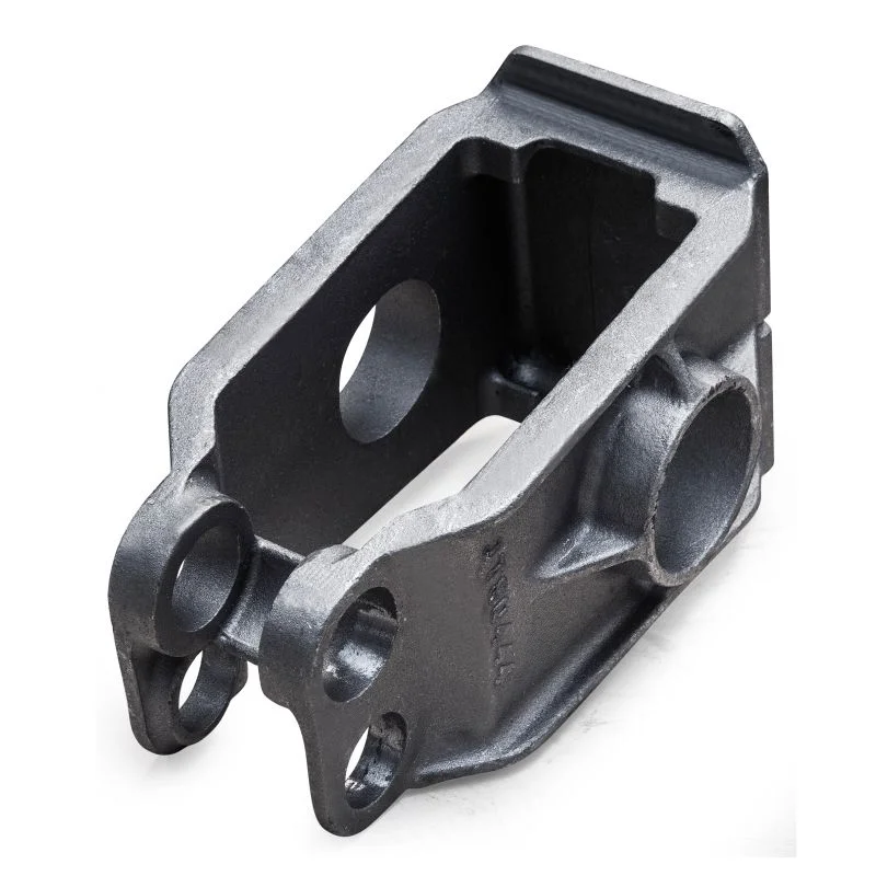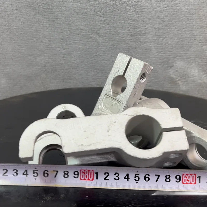
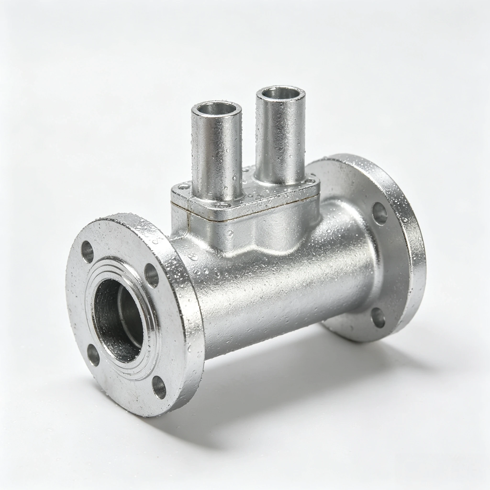
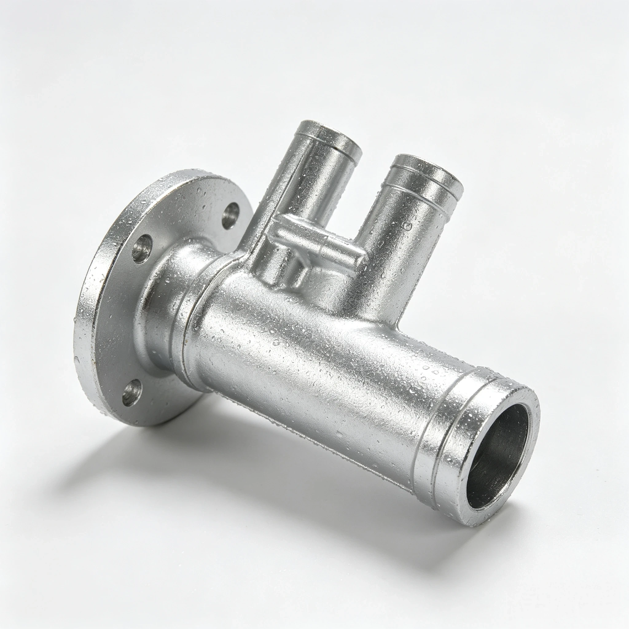
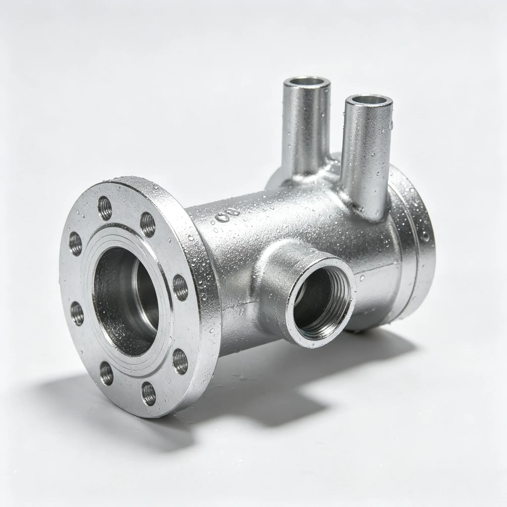
Custom Aluminum Multi Way Manifold Valve Housing Fluid Pipe Sand Die Cast Parts with CNC Micro Machining
Direct factory support
Get a quote that fits your project
Send your drawing or product reference, material grade and required quantity. Relia will review the requirements with you.
- Drawing & specification review
Confirm the supply scope and critical requirements.
- Samples before custom production
Review inspected samples before approving a batch.
- Inspection documents
Agree material and dimensional records for your part.
-
CNC Machining or NotCNC MachiningTypeLaser Machining, Milling, Turning, Wire EDM
-
Material CapabilitiesAluminum, Brass, Bronze, Copper, Precious Metals, Stainless Steel, Steel AlloysMicro Machining or NotMicro Machining
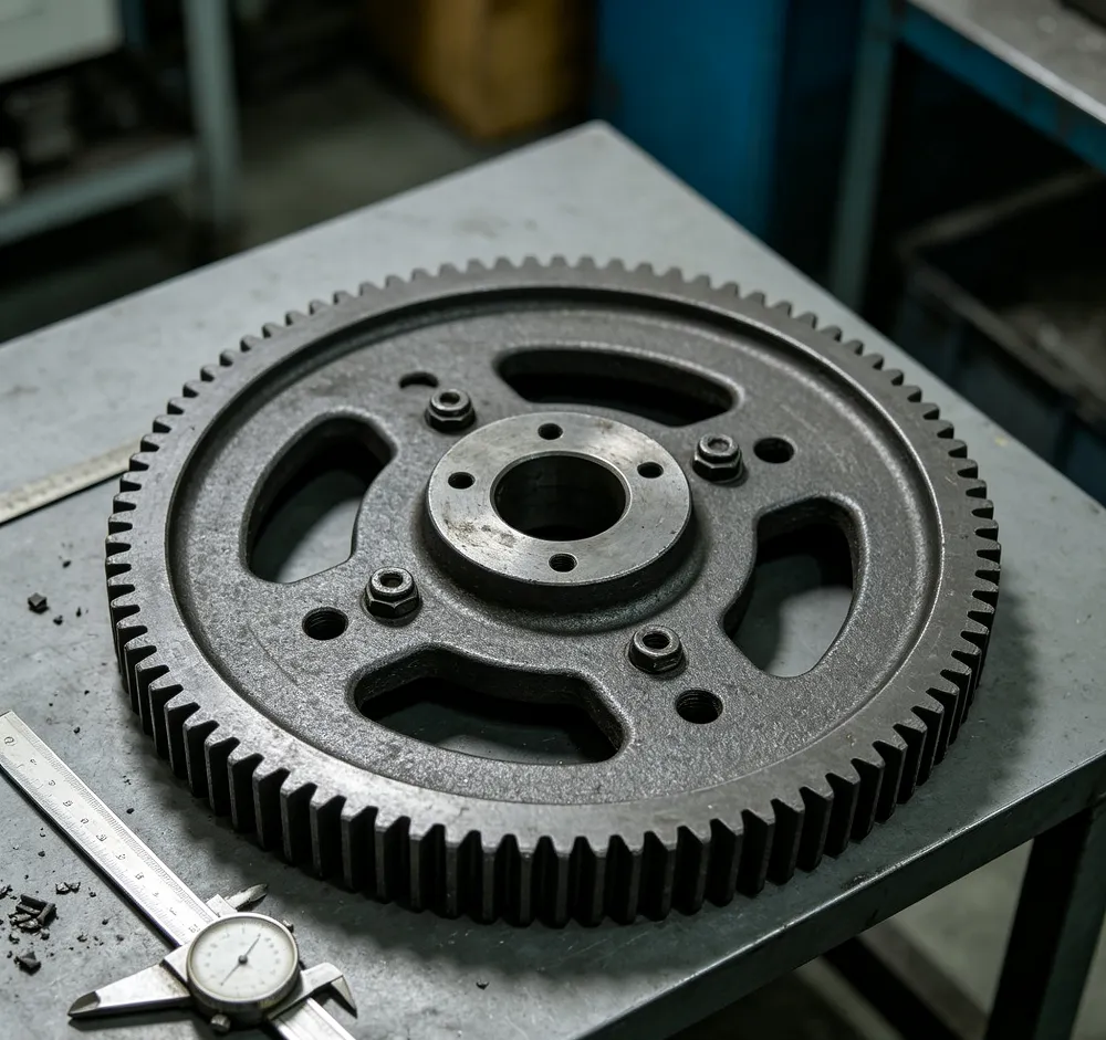
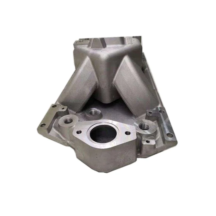
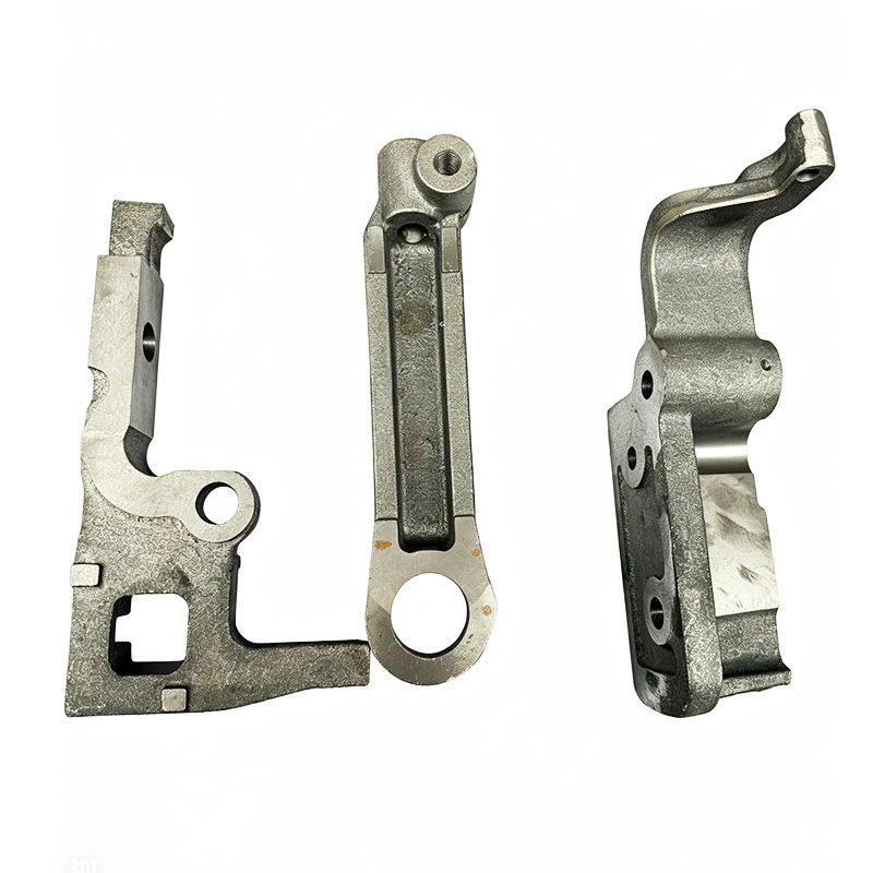
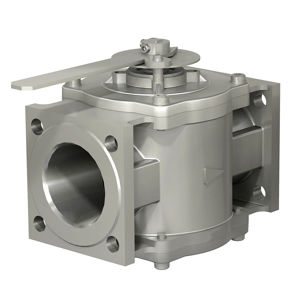
Multi-way aluminum manifolds, valve housings and fluid-pipe components can be requested through sand or die casting with CNC and micro-machining. Select the complete alloy and compatible route for the actual item. Define its supplied condition around the chosen fluid-system design and working duty.
Describe the manifold’s port arrangement
Show port positions and mating relationships with adjoining fluid components. Mark mounting and locating references and the dimensions governing installation. Specify the actual fluid, duty and acceptance criteria needed for that selected design rather than assuming pressure or compatibility ratings.
Scope the machining method and material
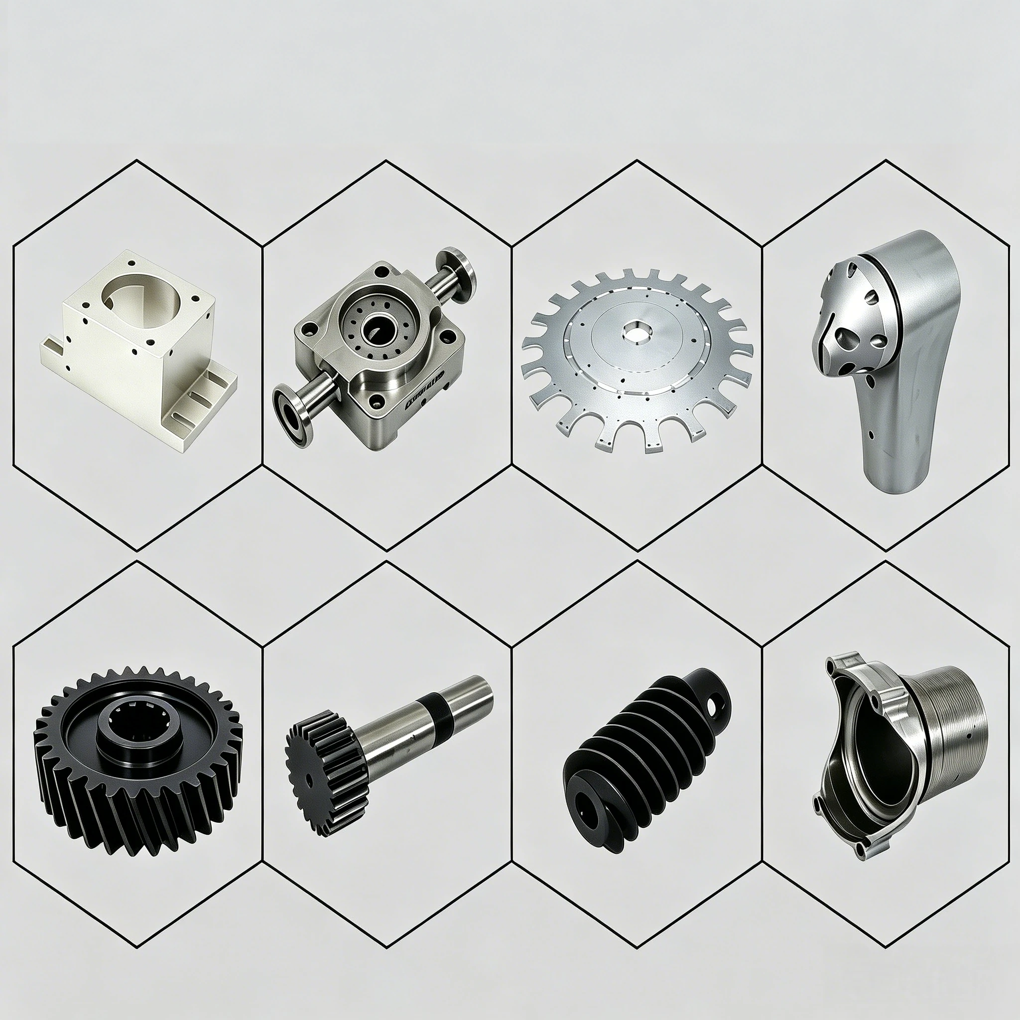
Laser machining, milling, turning and wire EDM are named operations. Other machining materials include brass, bronze, copper, precious metals, stainless steel and steel alloys. Assign each separate component its complete grade, incoming form and compatible operation.
Define final interfaces and surfaces
Distinguish cast-state regions from contacts requiring a finished CNC result. Establish dimensional limits and measurement conditions for relationships assessed together during approval. Identify the surface and appearance requirements relevant to the manifold or separate component’s supplied state.
- State manifold or separate part quantity and the controlling revision.
- Identify material, dimensional and surface acceptance records.
- Explain what an initial item must demonstrate at its fluid-system interfaces.
- Retain accepted grade, port and processing decisions within the component definition.
Use the approved geometry and actual service requirements when confirming further manifold or fluid-pipe component requests.