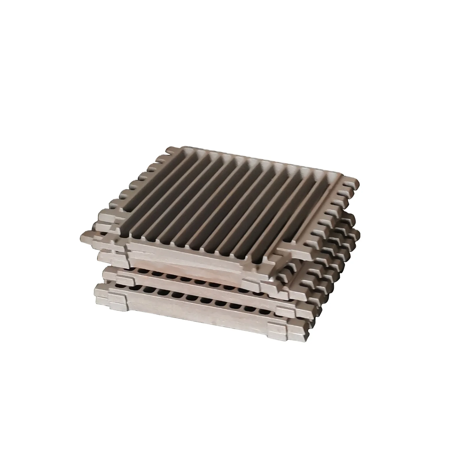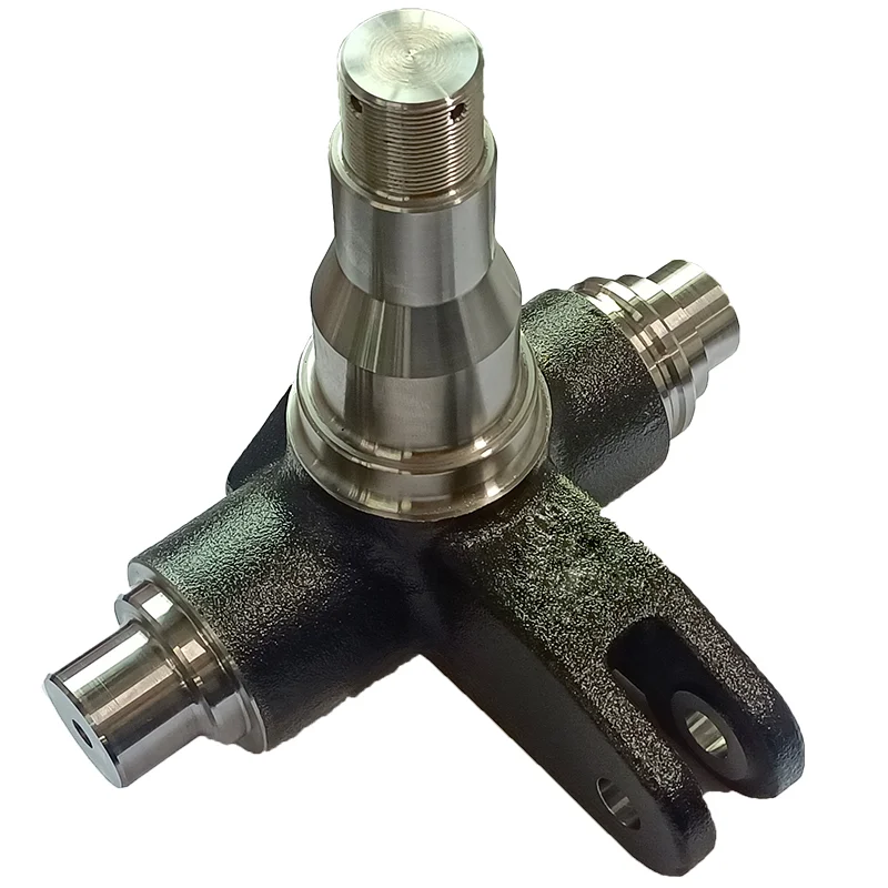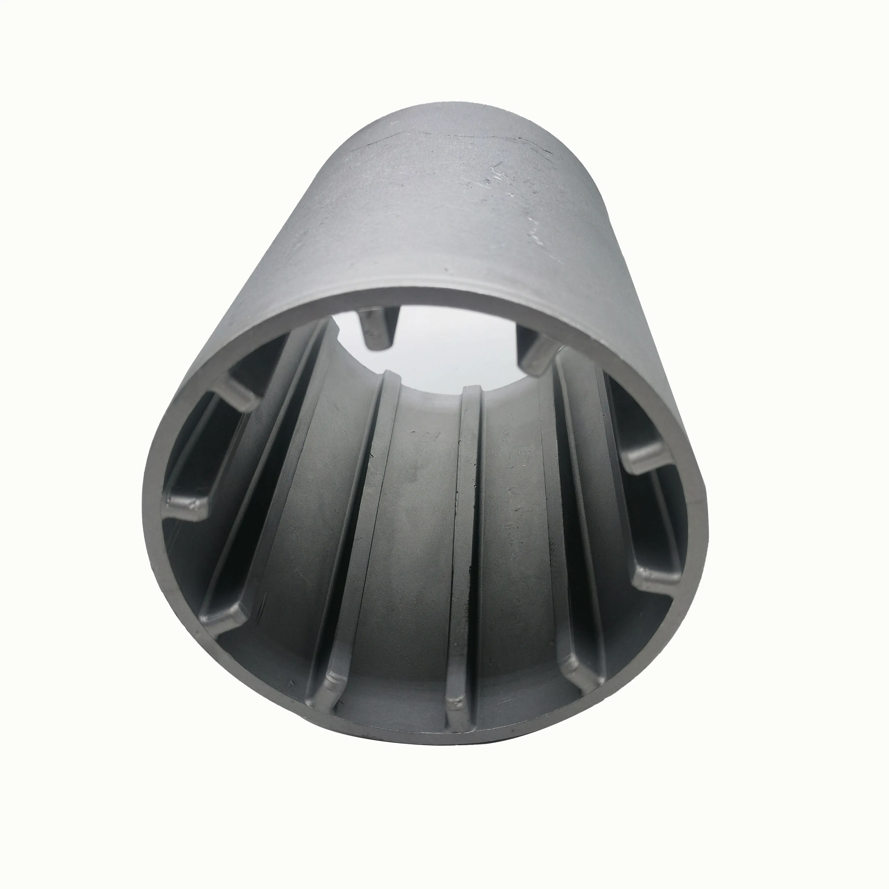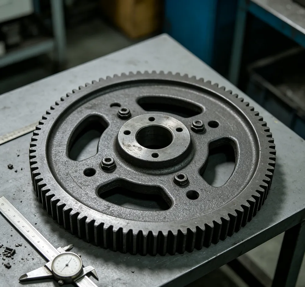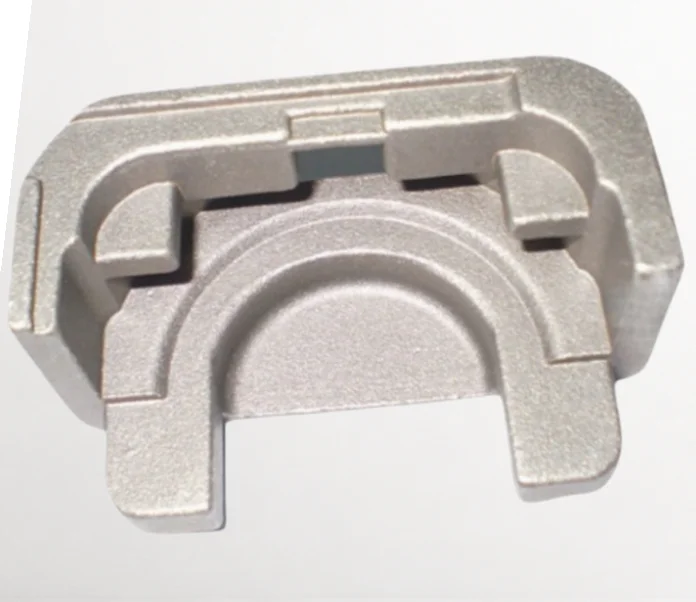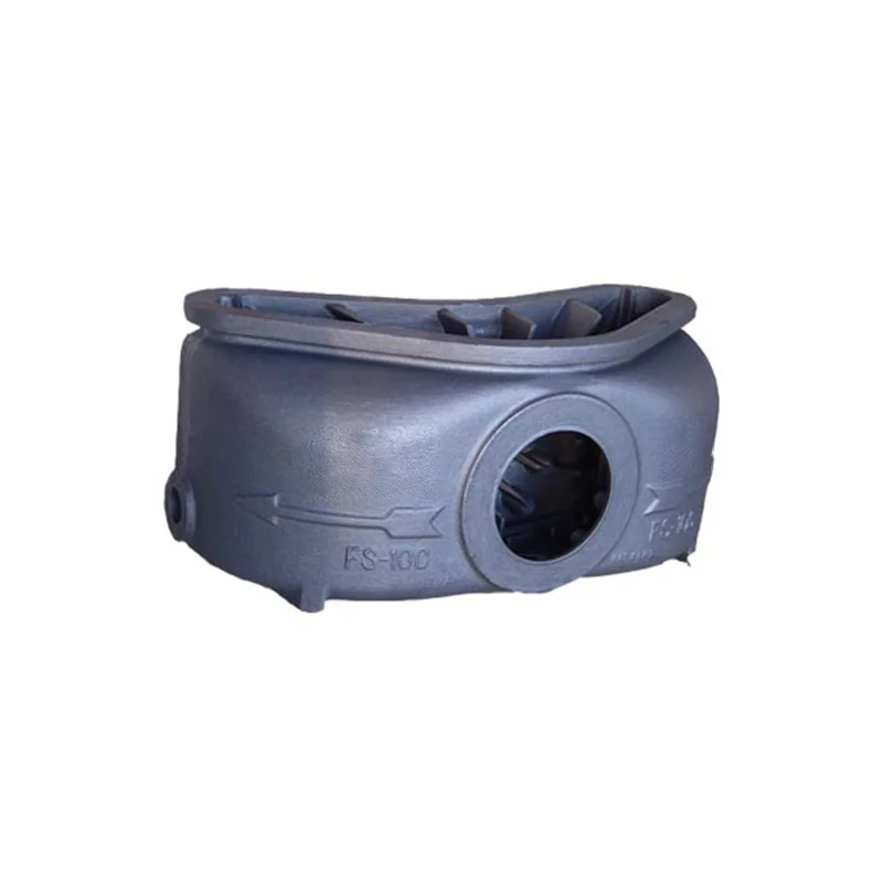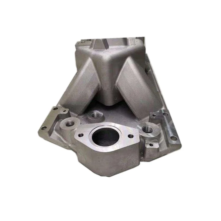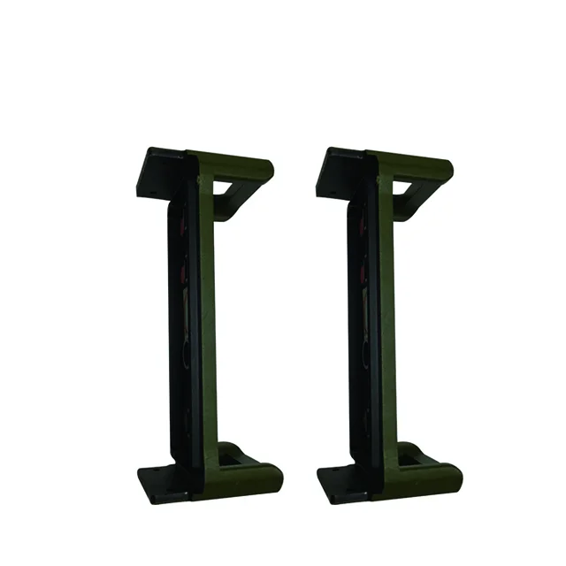
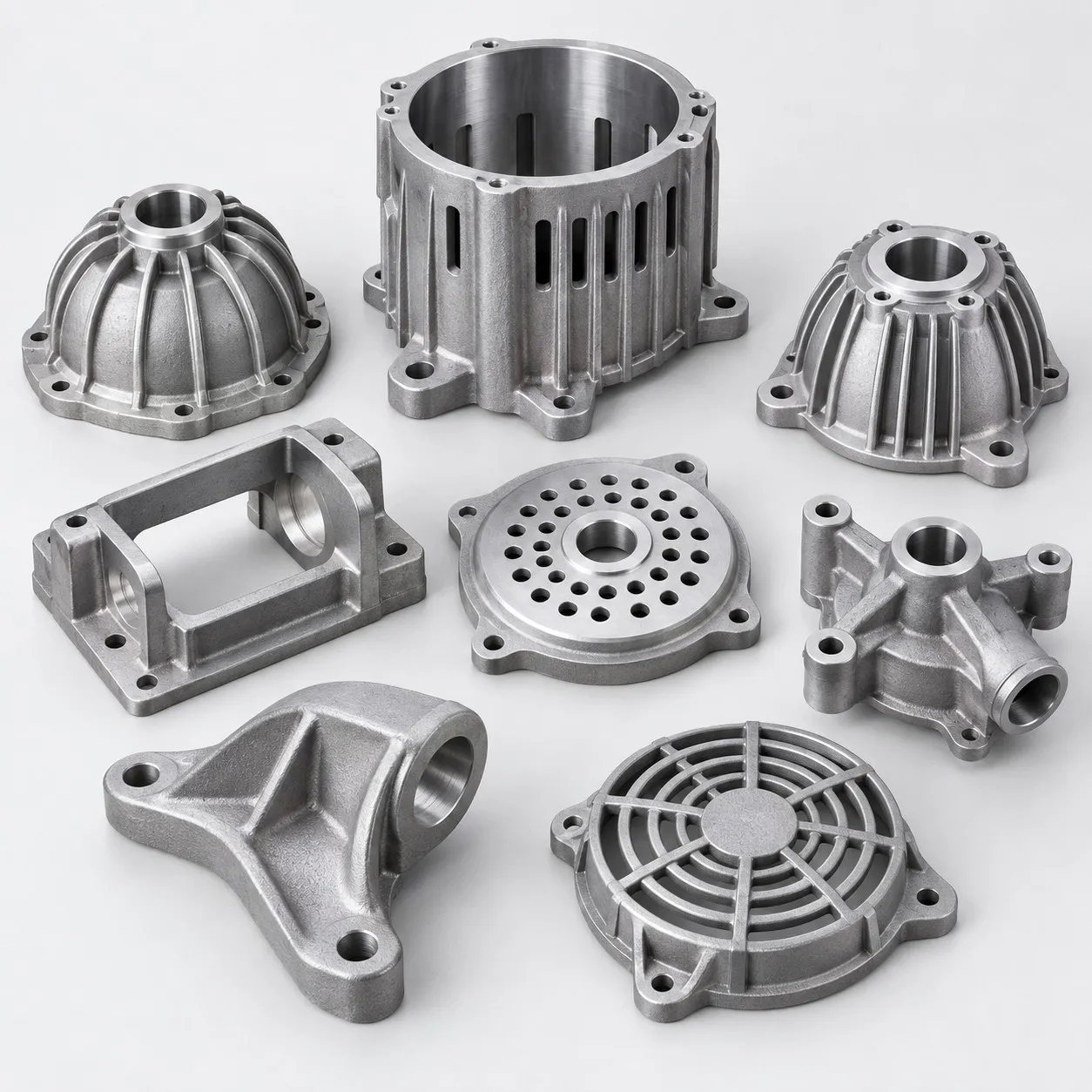
Custom OEM ODM Aluminum Sand Die Cast Parts and Separate Stainless Ductile Iron Castings with Tooling and Prototyping
Direct factory support
Get a quote that fits your project
Send your drawing or product reference, material grade and required quantity. Relia will review the requirements with you.
- Drawing & specification review
Confirm the supply scope and critical requirements.
- Samples before custom production
Review inspected samples before approving a batch.
- Inspection documents
Agree material and dimensional records for your part.
-
Casting MethodDie Casting
-
MaterialStainless Steel, Ductile Iron, Aluminum, Spectrometer AnalysisSurface TreatmentShot Blasting, Powder Coating, Hot Dip Galvanized, E-coating, Painting
-
Tolerance & Surface RoughnessCT4-CT6 (Investment), CT10-CT12 (Sand), Ra 1.6-3.2 (Smooth Finish)Tooling & Mold DesignIn-house Tooling Design, Mold Manufacturing, Prototyping Service
-
Service TypeOEM/ODM Custom Manufacturing / PrototypingDrawing FormatsSTEP, STP, IGES, DXF, DWG, PDF
-
CertificationISO 9001, IATF 16949 , AS 9100 , CE, RoHSQuality Control100% Inspection, CMM, Projector, Caliper, Salt Spray Test
-
Lead Time7-10 Days (Prototype), 15-25 Days (Mass Production)
OEM/ODM enquiries include aluminum, stainless-steel and ductile-iron components with material-appropriate sand, investment or die-casting routes. Tooling design, mould manufacturing and prototyping are available. Define the component, tool and prototype deliverables as part of the requested manufacturing scope.
Assign dimensional limits by casting route
For an investment-cast selection, the tolerance reference is CT4–CT6. Sand-casting acceptance references CT10–CT12 for the specified cast geometry. The surface reference is Ra1.6–3.2; agree its unit, controlled areas and measurement stage for the actual finished component.
Choose a compatible surface result
Finishes include shot blasting, powder coating, hot-dip galvanizing, e-coating and painting. Define coverage, masking and contact conditions for the selected material. Identify the appearance and functional surface requirements that the approval part must demonstrate.
- Drawings can be supplied as STEP, STP, IGES, DXF, DWG or PDF.
- Specify spectrometer analysis and the required material records.
- Assign CMM, projector and caliper checks to controlled dimensions.
- Define salt-spray testing and its actual acceptance conditions.
Link prototype approval to production inspection
The stated 100% inspection should address the agreed component characteristics and records. Request applicable ISO9001, IATF16949, AS9100, CE and RoHS documents with their actual scope. Identify the drawing revision and quantity, keeping prototype conclusions and any approved tooling changes connected to the production part definition. State what the prototype must prove before authorizing the agreed tool and component manufacturing scope.