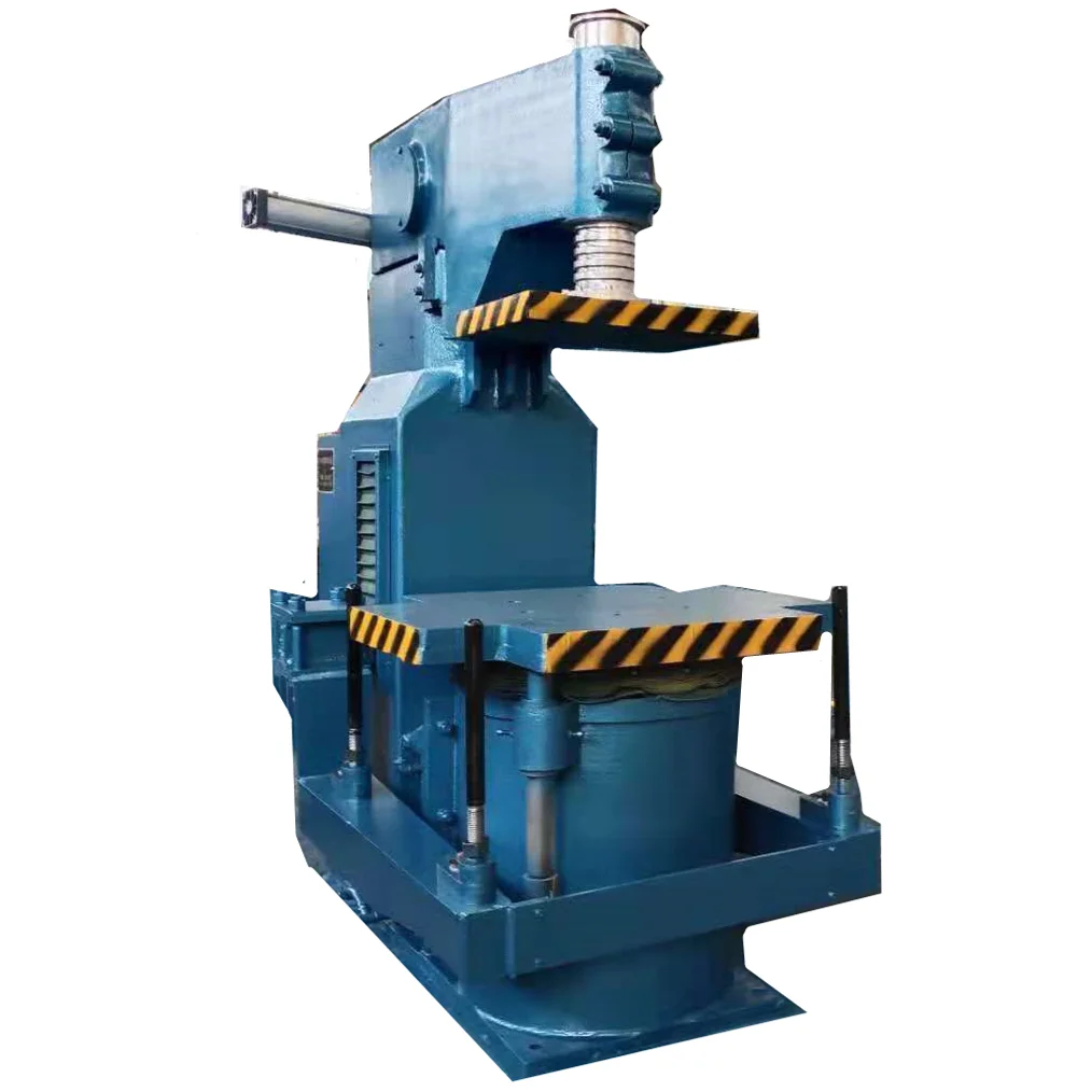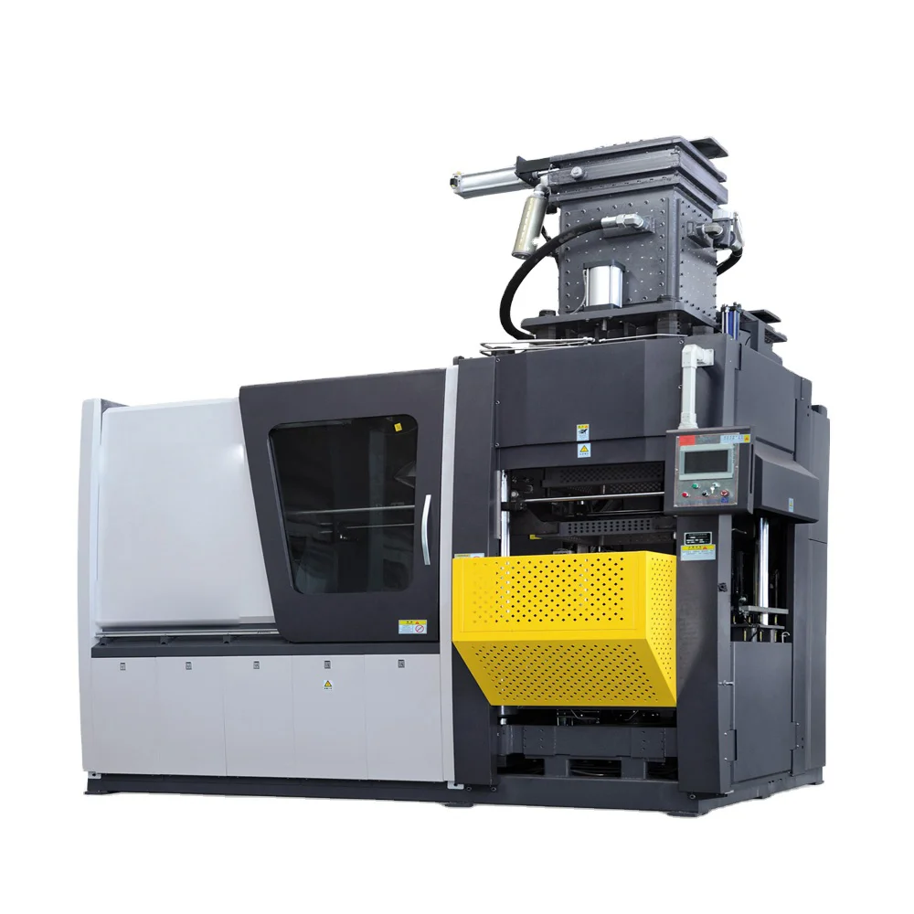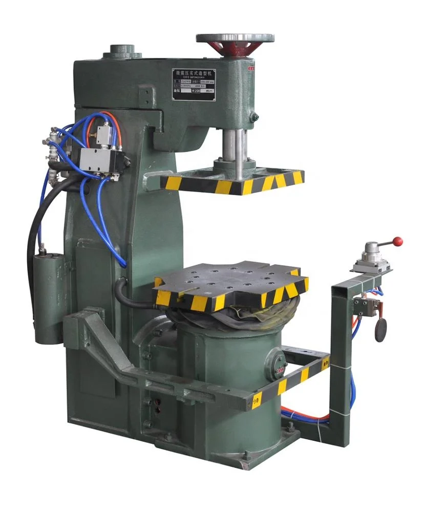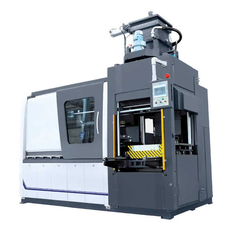
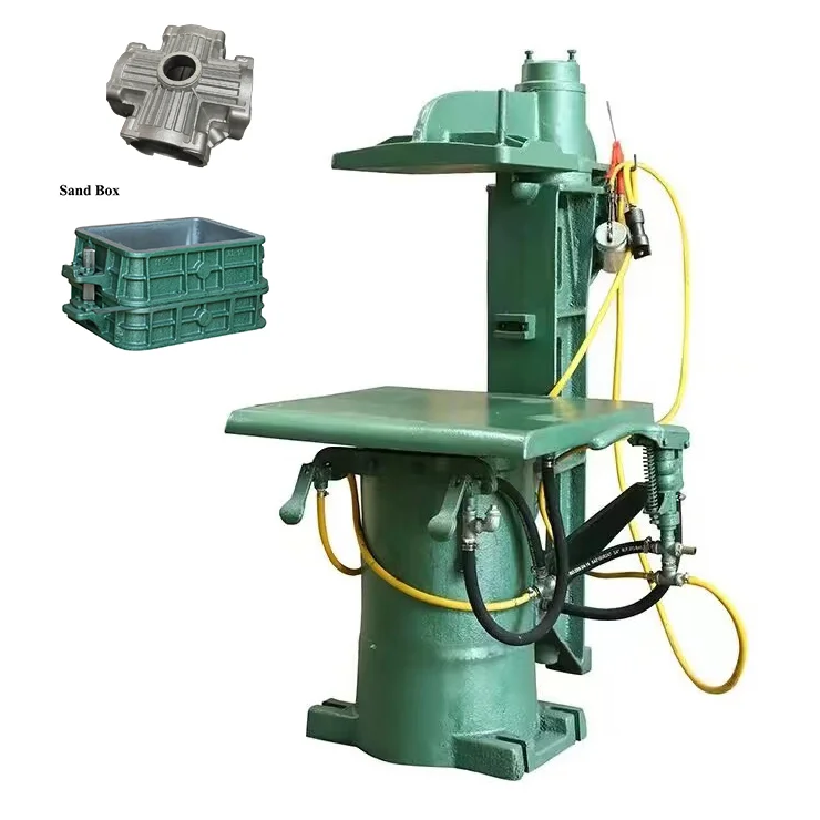
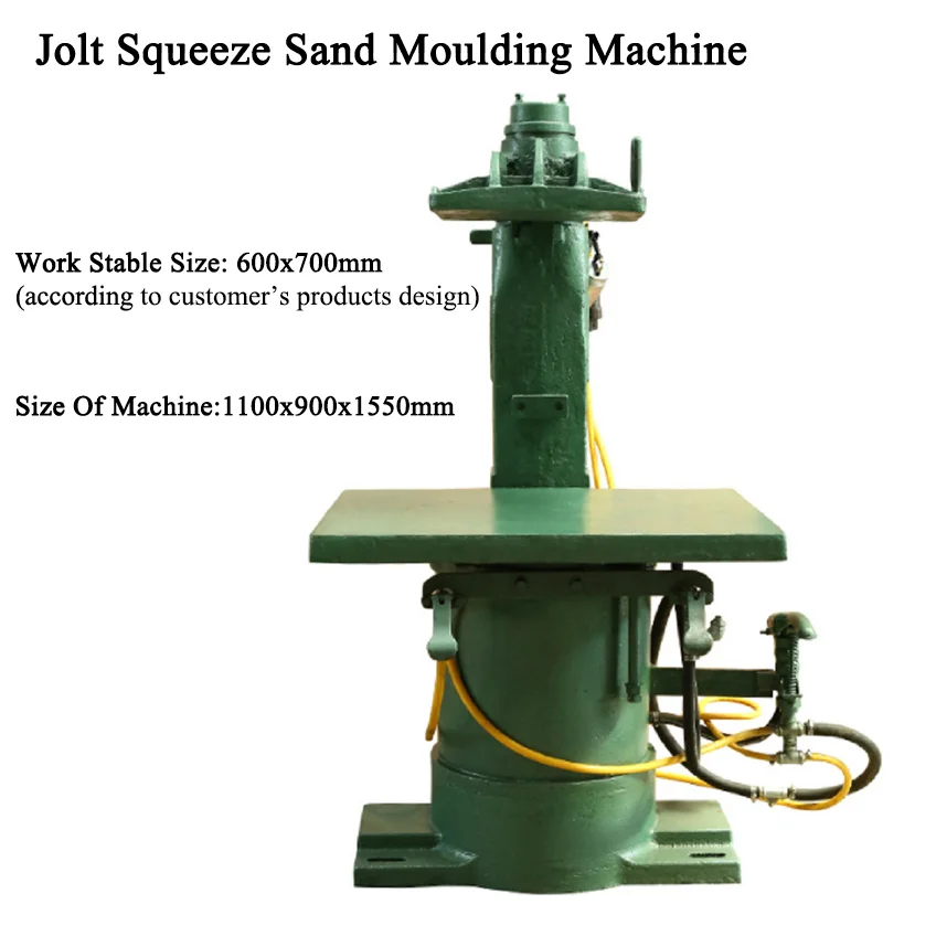
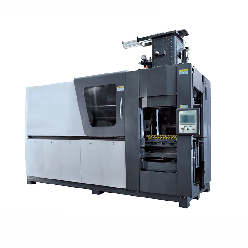
DL-Z145-I Green Sand Jolt Squeeze Foundry Moulding Machine for Iron Nonferrous Valve Fire Pump Auto Plumbing Mould Enquiries
Direct factory support
Get a quote that fits your project
Send your drawing or product reference, material grade and required quantity. Relia will review the requirements with you.
- Drawing & specification review
Confirm the supply scope and critical requirements.
- Samples before custom production
Review inspected samples before approving a batch.
- Inspection documents
Agree material and dimensional records for your part.
-
machine typejolt squeeze molding machine, sand molding machinevideo outgoing-inspectionProvided
-
machinery test reportProvidedcore componentsPLC, Engine, Bearing, Gearbox, Motor, Pressure Vessel, Gear, Pump
-
voltage380V 50HZpower(w)10 KW(13.41hp)
-
dimension(l*w*h)850 * 700 * 1380 mm(33.46*27.56*54.33in)warranty1 year
-
key selling pointsCompetitive Priceweight (kg)500
-
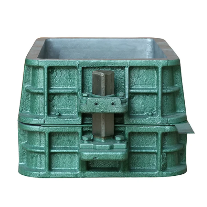
Typemetal sand molding machineThe Size Of Sand Mold300 * 400*150/100 ( mm )
-
The Size of Table470*540mmThe Jolting Power380 force
-
Compaction Stroke110mmApplicationNon-ferroalloy Casting
-
TechnologyGreen Sand Casting TechnologyFoundry MachineJolt Molding Machine Casting Machine
-
FeatureSand Core Shooting Making MachineFunctionJolt Squeeze Sand Moulding Machine
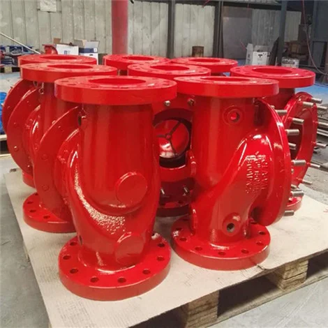
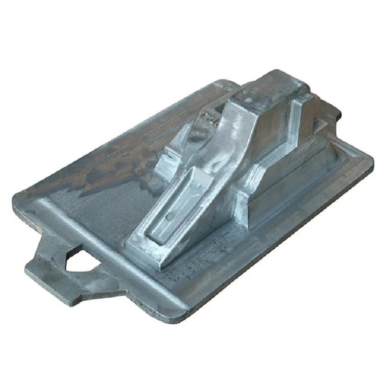
DL-Z145-I green-sand jolt-squeeze equipment is offered for selected iron or nonferrous casting moulds, including valve, fire-pump, automotive and plumbing projects. Define the pattern interfaces, sand conditions and actual moulding task for the equipment being ordered.
Choose mould geometry and compaction requirements
The mould-size reference is 300 × 400 × 150/100 mm; agree the selected height arrangement. Table size is 470 × 540 mm and compaction stroke is 110 mm. The jolting reference is 380 force, with its unit and operating basis to define for acceptance.
Plan the machine and plant connections
Electrical references are 380 V, 50 Hz and 10 kW, or 13.41 hp. Overall dimensions are 850 × 700 × 1380 mm, also given as 33.46 × 27.56 × 54.33 in. Check installation clearances and utility connections against the selected equipment drawing.
- Core components include PLC, engine, bearing, gearbox, motor, pressure vessel, gear and pump.
- Identify the controls and interfaces within the supplied package.
- Where core shooting is required, define that function and any separate equipment.
- Specify operating checks and records for the actual moulding task.
Review the acceptance and warranty package
An outgoing-inspection video and machinery test report are provided. Agree the configuration and conditions they must demonstrate. A one-year warranty is listed subject to defined scope and terms. Retain the accepted model, mould requirements and utilities with the order so equipment approval and installation address the actual foundry configuration.