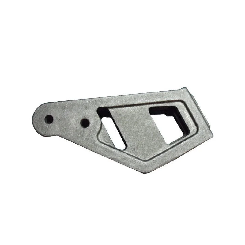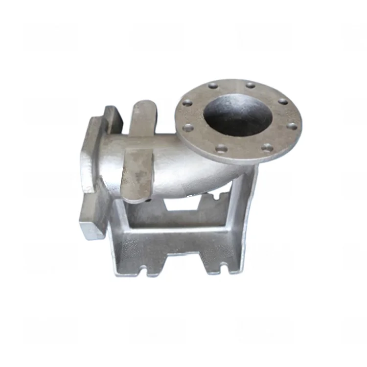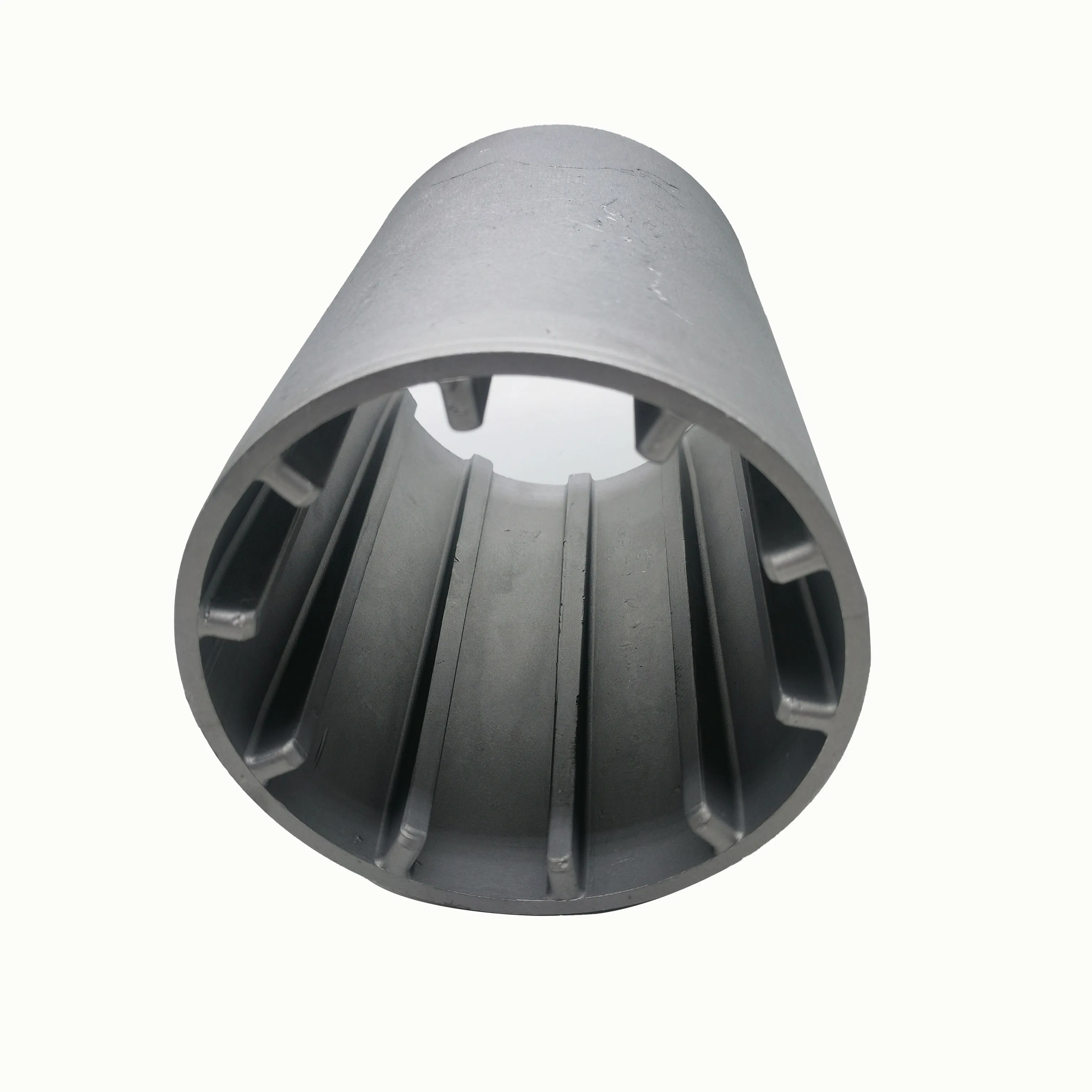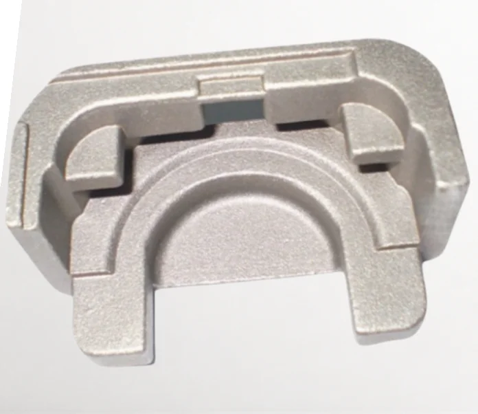
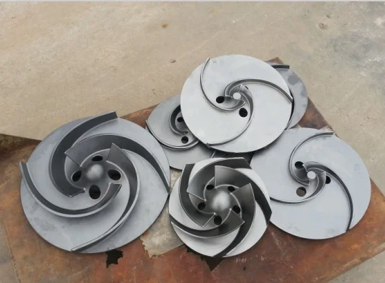
Custom Cast Iron Steel Motor Shell Sand Castings with Resin Coated Sand Cores CT6 and 3V DC Assembly Enquiries
Direct factory support
Get a quote that fits your project
Send your drawing or product reference, material grade and required quantity. Relia will review the requirements with you.
- Drawing & specification review
Confirm the supply scope and critical requirements.
- Samples before custom production
Review inspected samples before approving a batch.
- Inspection documents
Agree material and dimensional records for your part.
-
Materialcast iron cast steel
-
Product Namemotor shellApplicationIndustry Machine
-
Keywords3v Dc MotorFeatureCustomized
-
Processsand casting
-
SurfacesmoothToleranceCT6
-
ColorCustomer Request
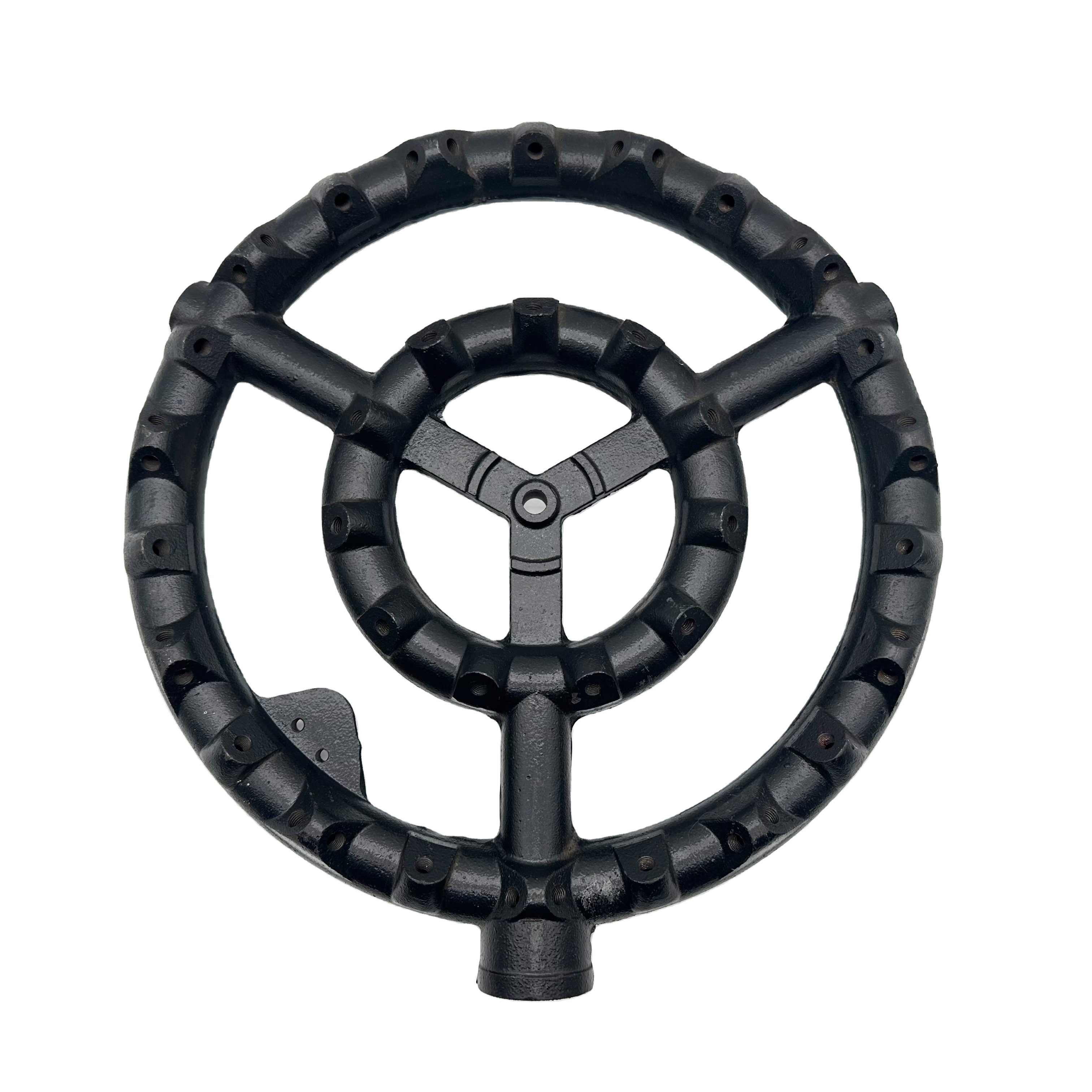
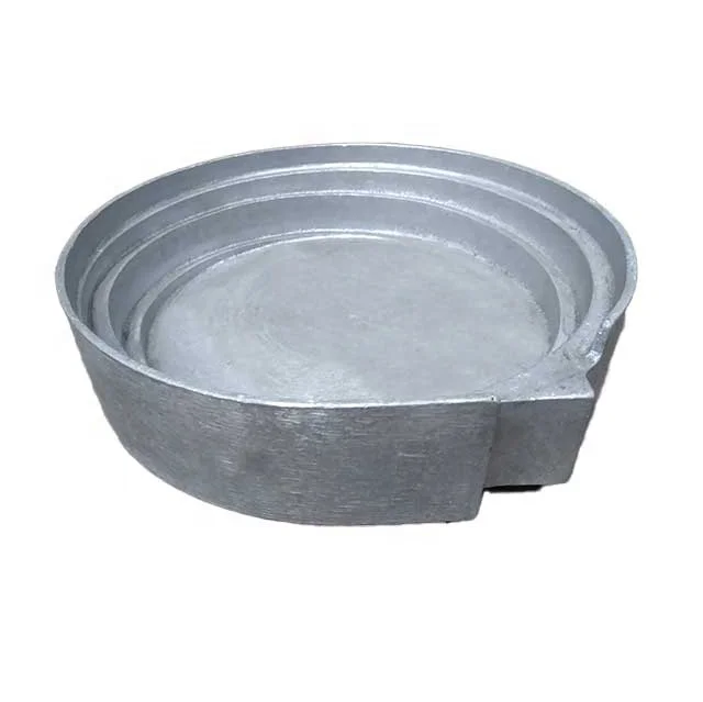
Custom cast-iron or cast-steel motor shells are offered with sand casting and resin-coated sand-core requests. The tolerance reference is CT6, with color selected by the customer. Identify the actual shell drawing, complete grade and required supplied condition for the intended assembly.
Define the motor-shell and core geometry
Show the locating, mounting and connection interfaces with the datums controlling fit. Identify internal geometry requiring a core and the resulting cast surfaces assessed for acceptance. For a 3 V DC motor-shell request, provide the actual assembly and its dimensional requirements.
Set casting-class and surface acceptance
Assign the stated class to affected casting features under the governing document. Distinguish cast-state dimensions from any required finished interfaces. A smooth surface is stated; define the roughness, appearance and inspection criteria needed for the selected supplied shell.
Make color and functional fit part-specific
Identify working contacts and visible areas with their final condition. Specify the chosen color and any treatment required by the design. Explain where surface requirements interact with mounting geometry or the interfaces assessed for operation.
- Provide quantity and the controlling component revision.
- Identify material and dimensional approval records.
- Define the purpose of an initial shell, including core and shell dimensions assessed together during acceptance.
- Retain accepted core and interface changes with the drawing.
Keep the grade, selected moulding requirement and final supplied state connected to approval of the actual motor housing.