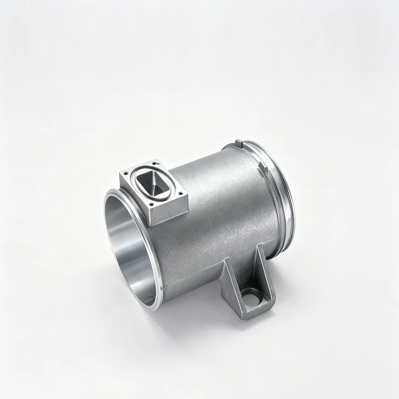
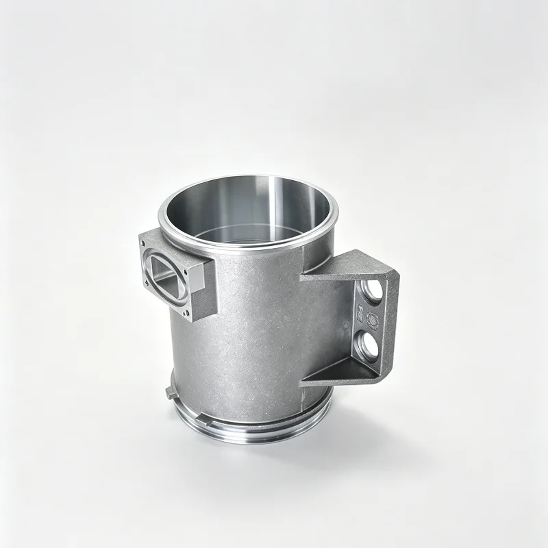
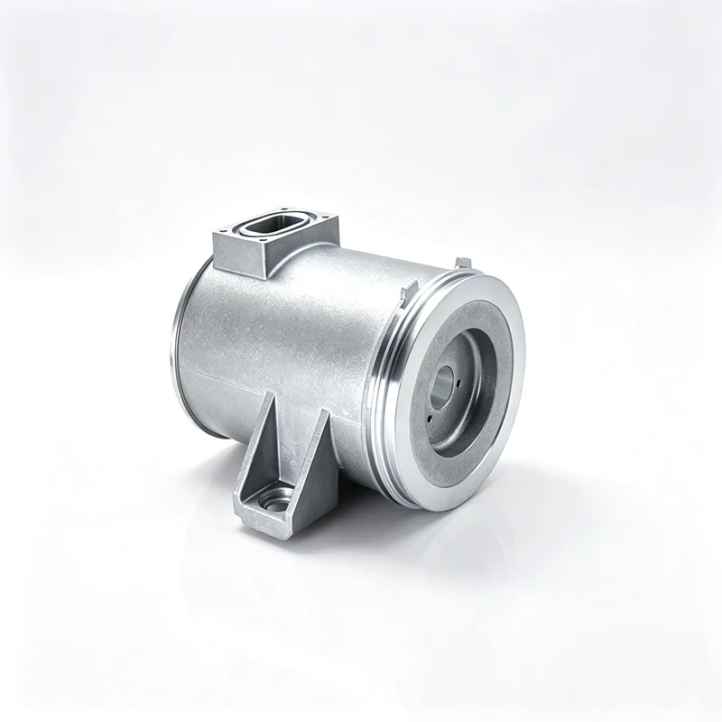
CAD-Based OEM/ODM CNC Milling, Drilling and Micro Machining — Separate Iron, Steel and Aluminum Casting Enquiries
Direct factory support
Get a quote that fits your project
Send your drawing or product reference, material grade and required quantity. Relia will review the requirements with you.
- Drawing & specification review
Confirm the supply scope and critical requirements.
- Samples before custom production
Review inspected samples before approving a batch.
- Inspection documents
Agree material and dimensional records for your part.
-
CNC Machining or NotCNC MachiningTypeMilling
-
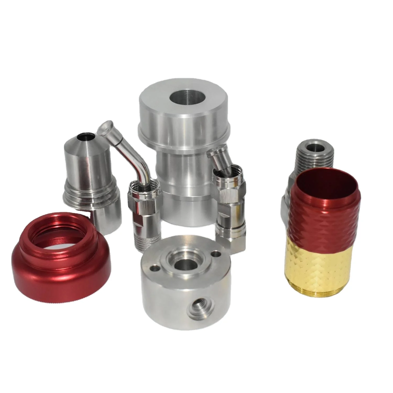
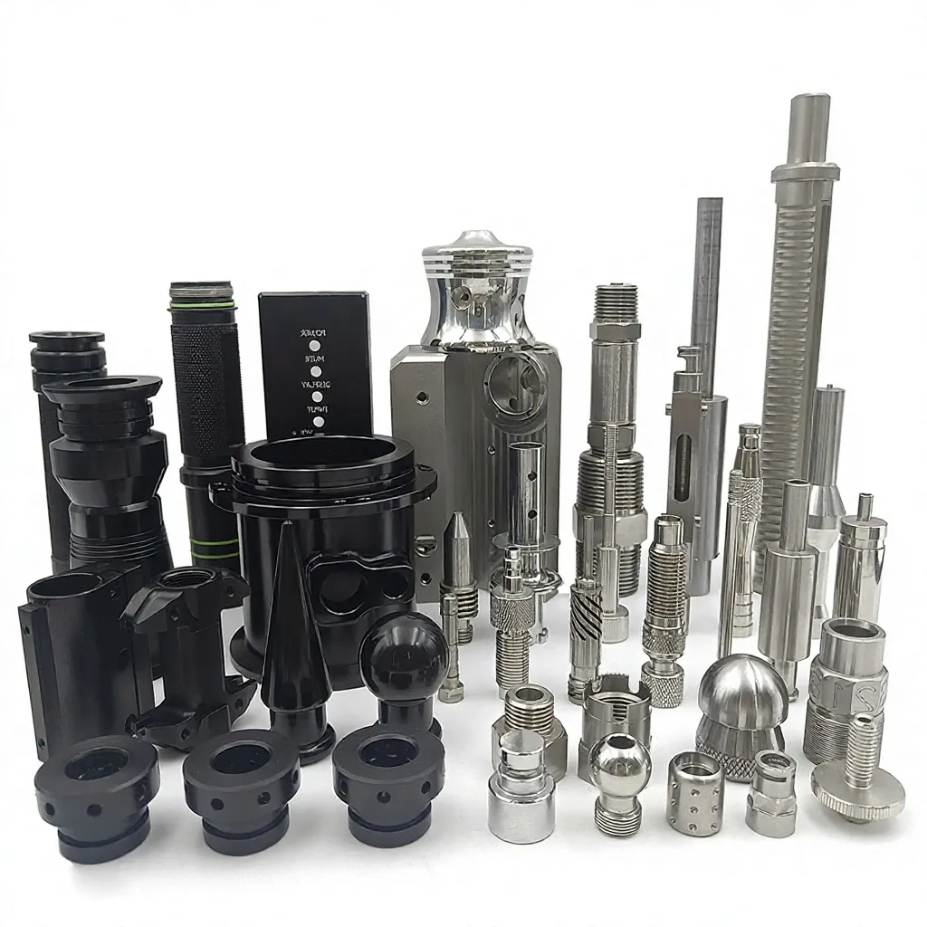
Material CapabilitiesAluminum, Brass, Copper, Stainless Steel, Steel AlloysMicro Machining or NotMicro Machining
-
Surface treatmentPainting\Powder Coating\Plating\PolishingEquipment3/4/5 Axis CNC Machining Center
-
Tolerance±0.005mm-±0.02mmServiceOEM ODM CNC Drilling Milling Machining Service
-
ApplicationMedical Device,part,Manufacture,Electrical application,DroneProcessing MethodCustom According to Provided CAD Drawings
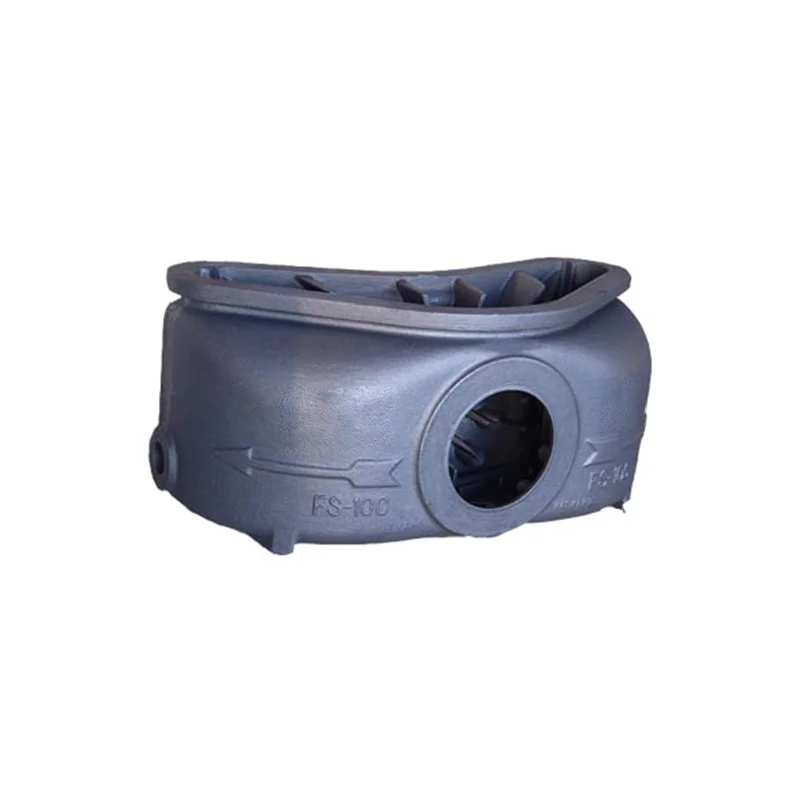
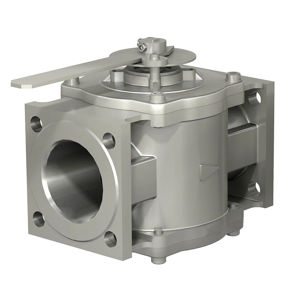
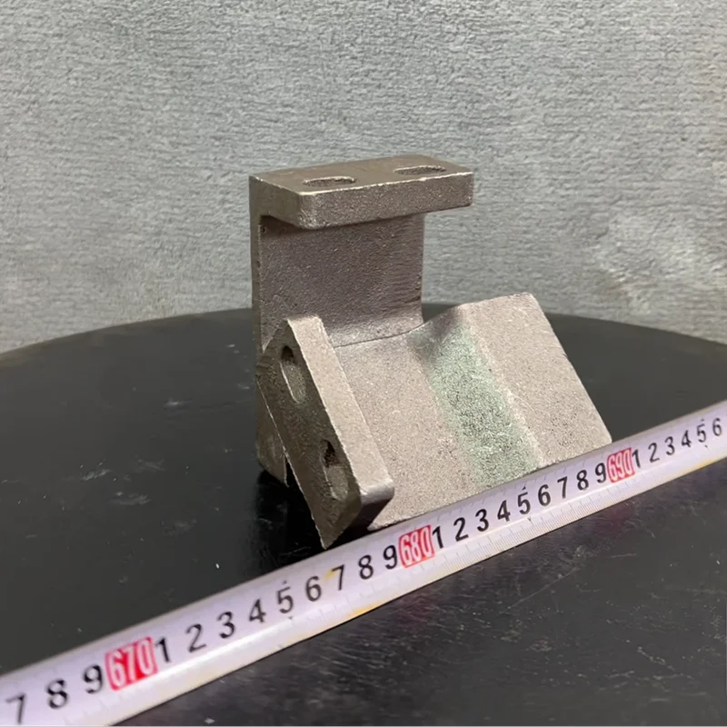
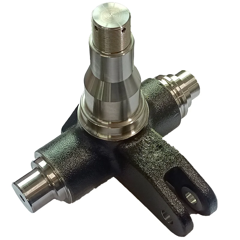
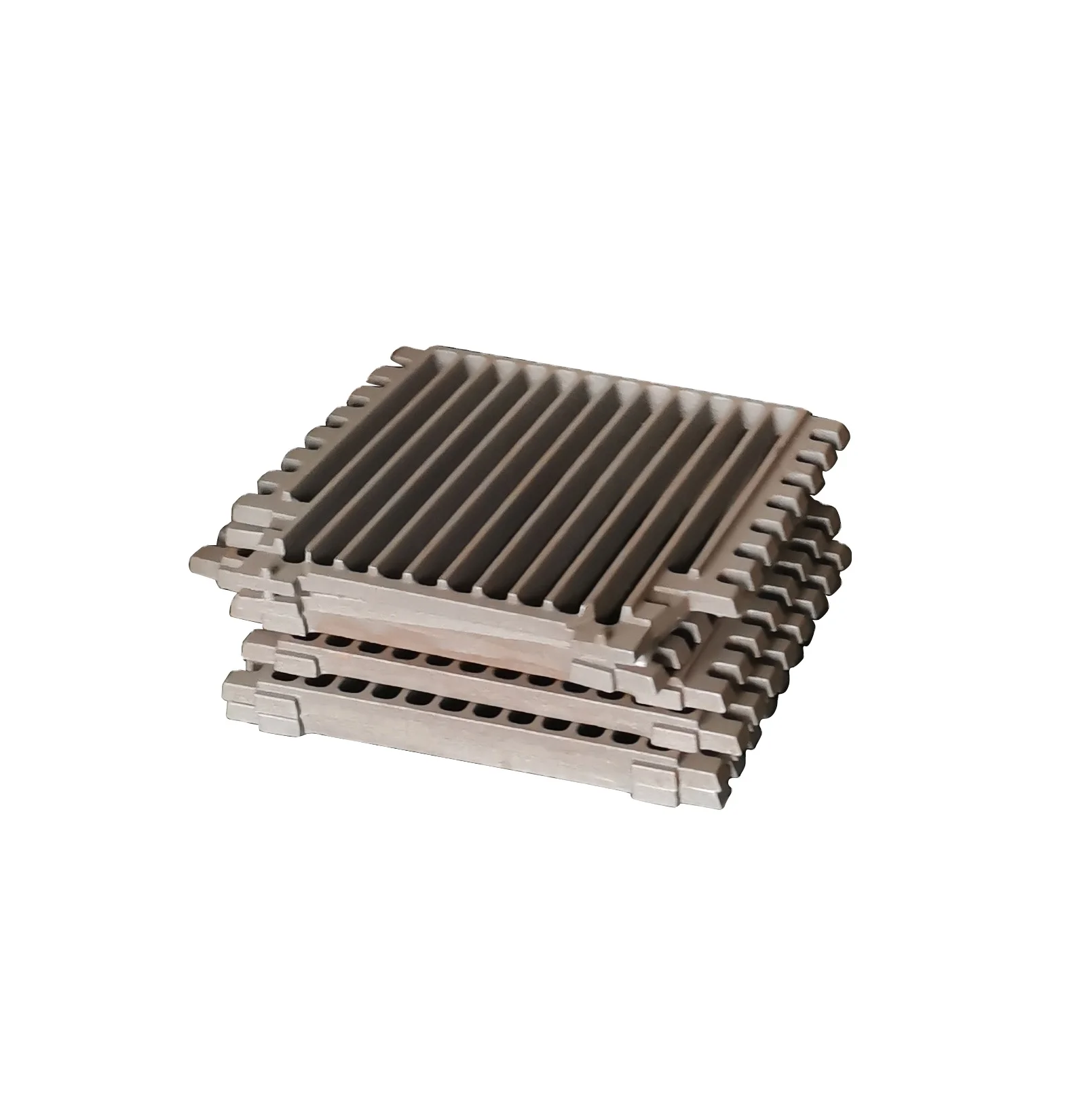
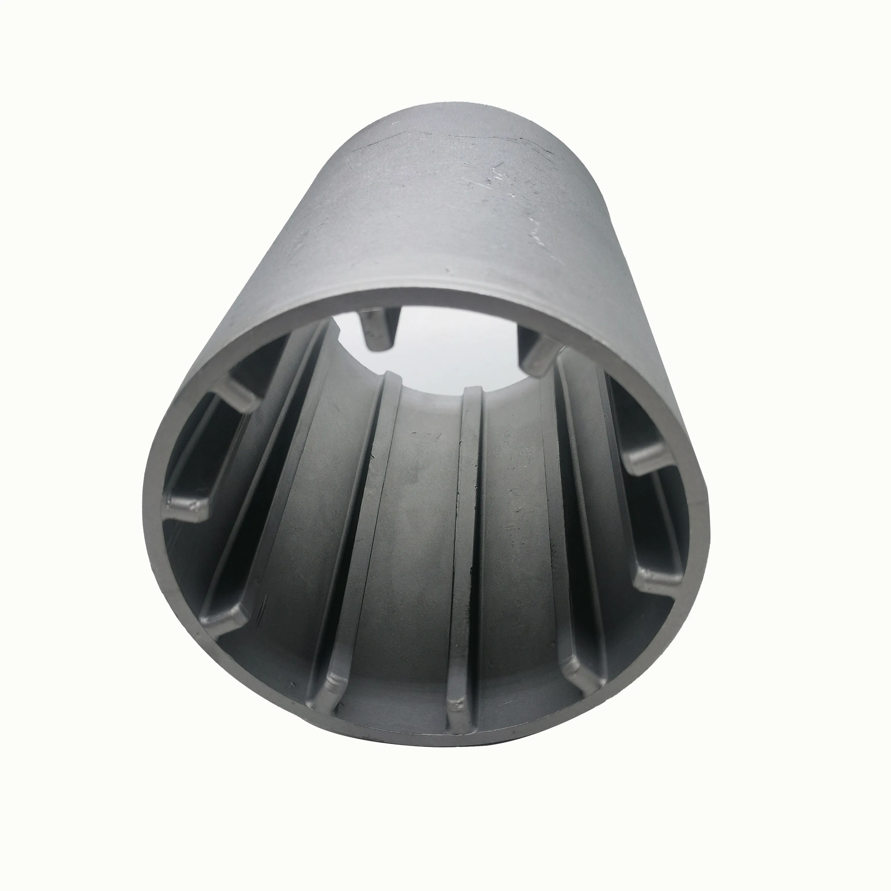
Supplied CAD drawings define the geometry for this OEM/ODM machining enquiry. The scope includes CNC milling, drilling and micro machining using 3-, 4- and 5-axis machining centers. Iron, steel and aluminum die-, sand- and investment-casting requests can be specified separately from the finished machining work.
Use the CAD drawing to control the finished dimensions
Identify the authoritative model and drawing revision. Mark the dimensions and datums needed to accept the finished part, including any micro-machined geometry. The stated machining-tolerance reference is ±0.005 mm to ±0.02 mm, with the appropriate limit selected for each controlled dimension and agreed inspection.
Select the material and blank for machining
Material capabilities include aluminum, brass, copper, stainless steel and steel alloys. Name the grade and required delivery condition for the actual component. If the enquiry includes a casting, define its material and die-, sand- or investment-casting route independently so the blank and secondary machining scope are clear.
- Provide the controlled CAD data and required quantity.
- Specify the material grade and incoming blank requirement.
- Allocate machining tolerances to the relevant dimensions.
- Describe the required finish and inspection acceptance.
Plan the finish around functional surfaces
Painting, powder coating, plating and polishing are named finishing options. Select the treatment for the component and identify interfaces requiring specific instructions. The acceptance drawing should describe the part in its final supplied condition, including dimensions affected by surface work.
Define the application-specific purchase requirements
Medical-device parts, manufacturing, electrical applications and drones are enquiry areas. State the component's intended use and any required approvals or documentation for that project. The drawing, material and acceptance criteria should establish the ordered part rather than an application label alone.