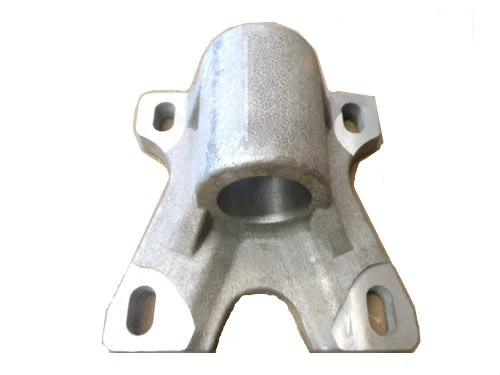
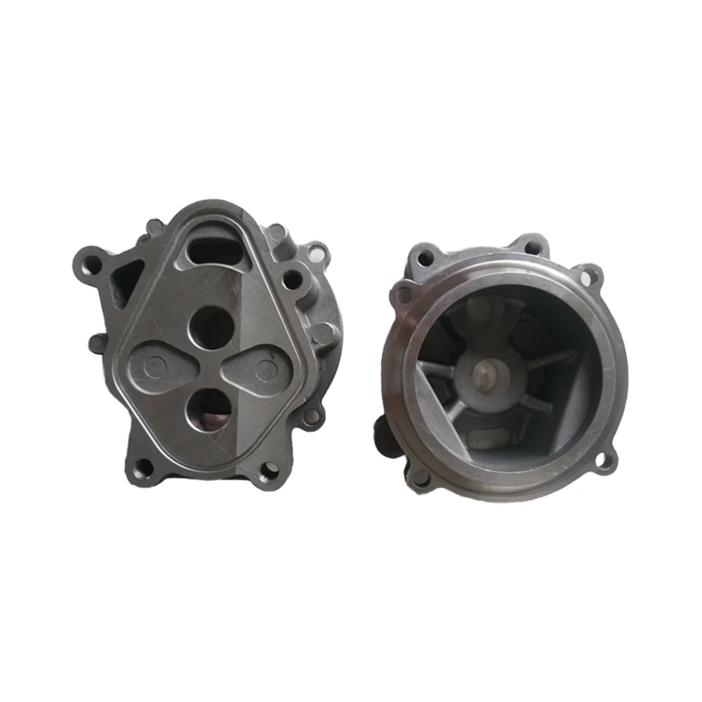
Relia OEM Aluminum Die, Sand and Gravity Casting Services with ISO9001 Documentation
Direct factory support
Get a quote that fits your project
Send your drawing or product reference, material grade and required quantity. Relia will review the requirements with you.
- Drawing & specification review
Confirm the supply scope and critical requirements.
- Samples before custom production
Review inspected samples before approving a batch.
- Inspection documents
Agree material and dimensional records for your part.
-
materialaluminum,stainless steel.steel alloy,bronze brass
-
sizeas per customer's drawing requiredToleranceas per customer's drawing request
-
Processmold development /3D print shell +casting +cnc machinining+ deburrQualityISO 9001:2000 TS16949 Standard
-
Casting ToleranceCT 4-6 ct7-8 ct 9Drawing formatPDF/CAD/3D/STP/STEP
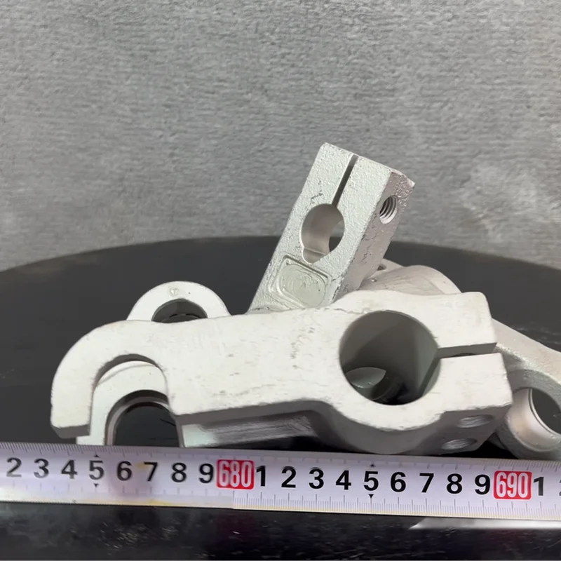
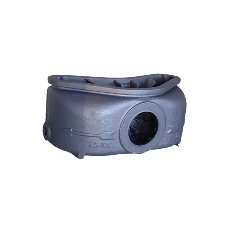
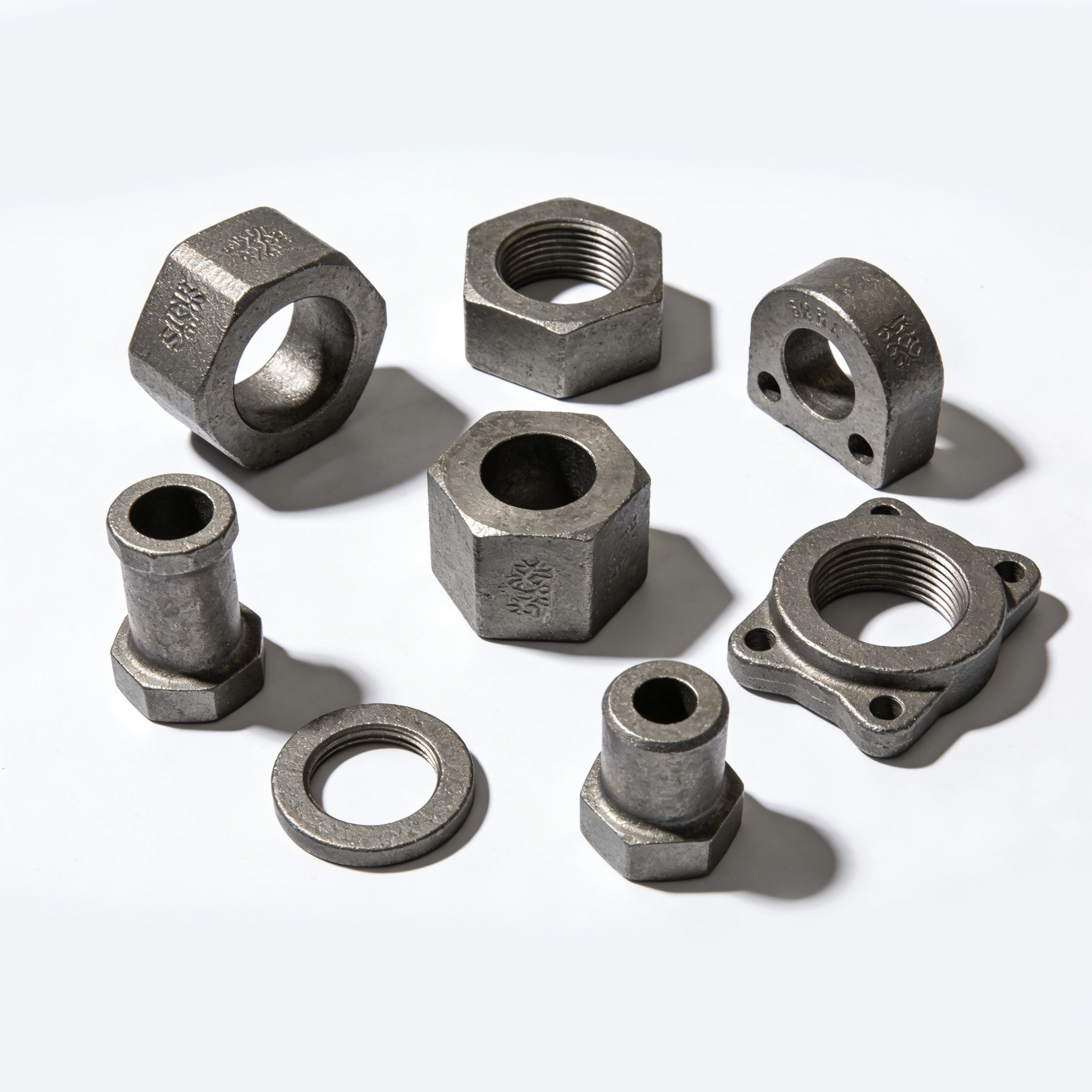
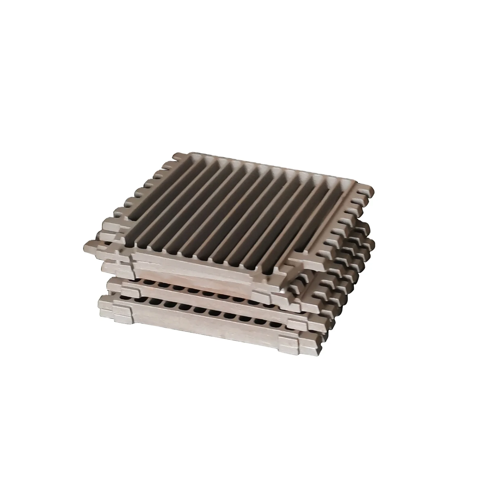
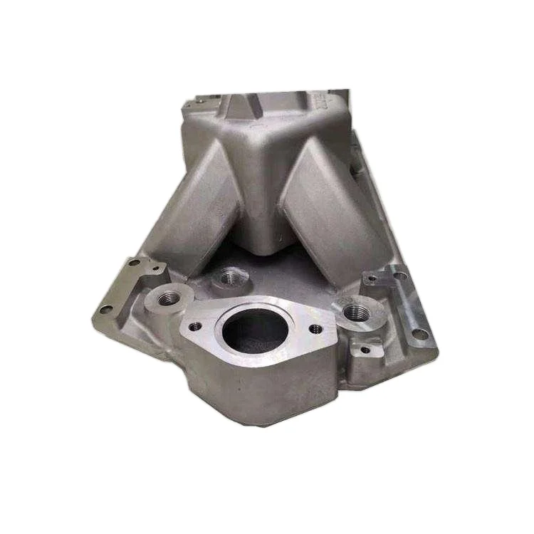
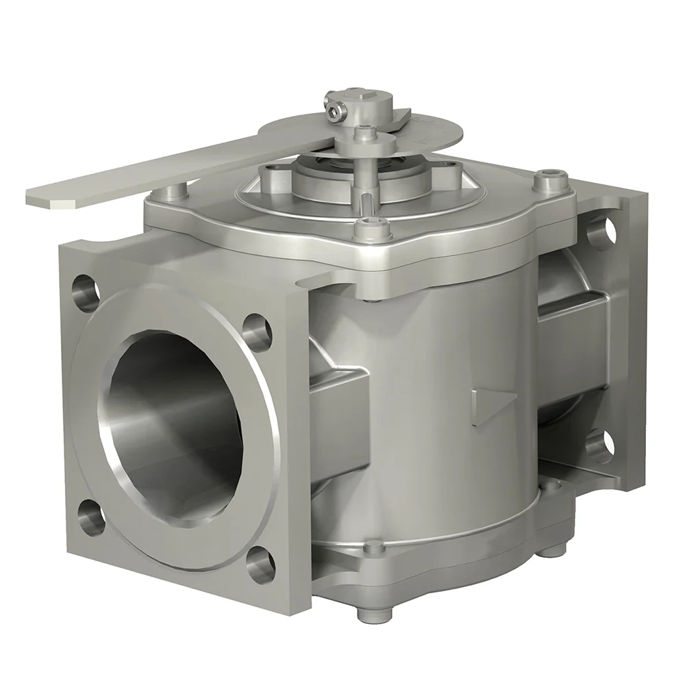
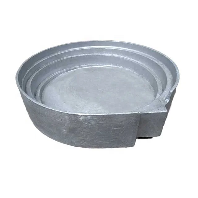
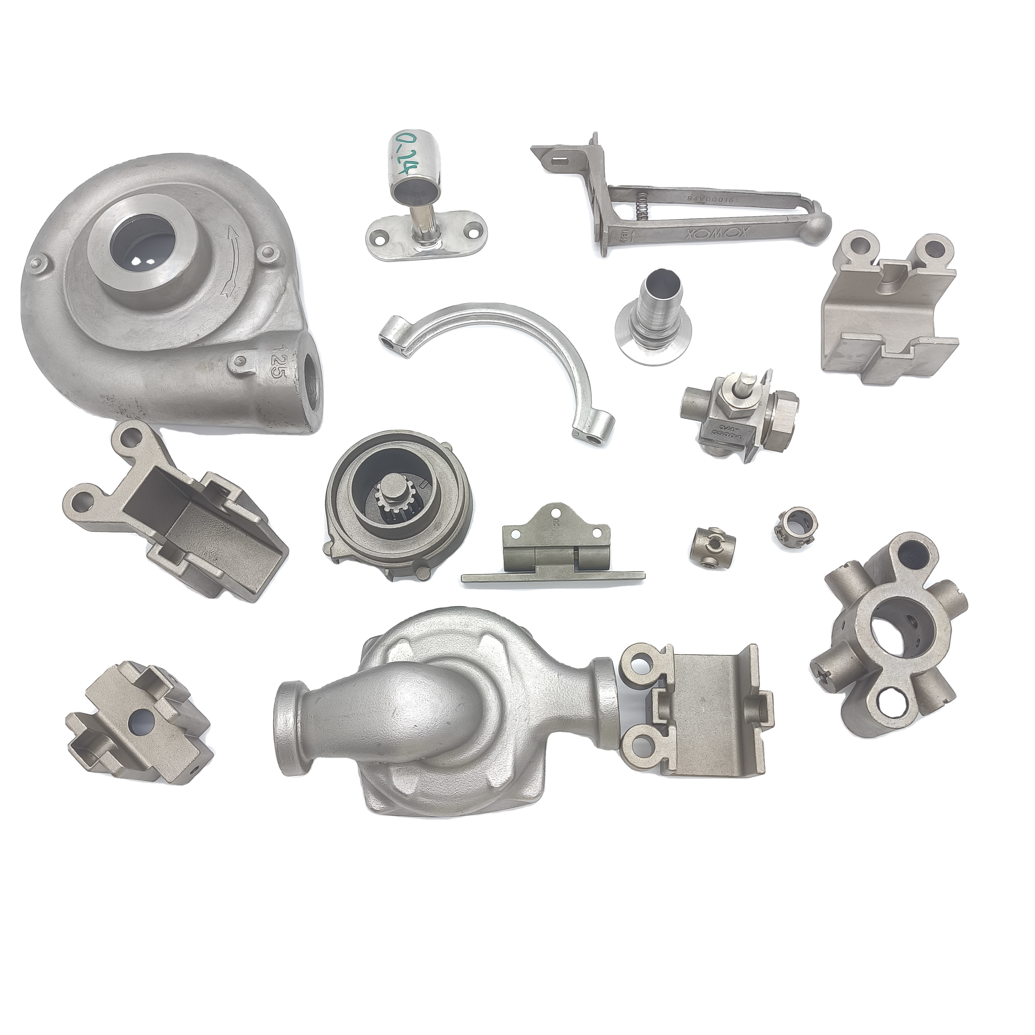
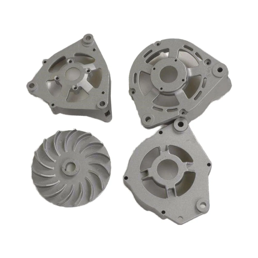
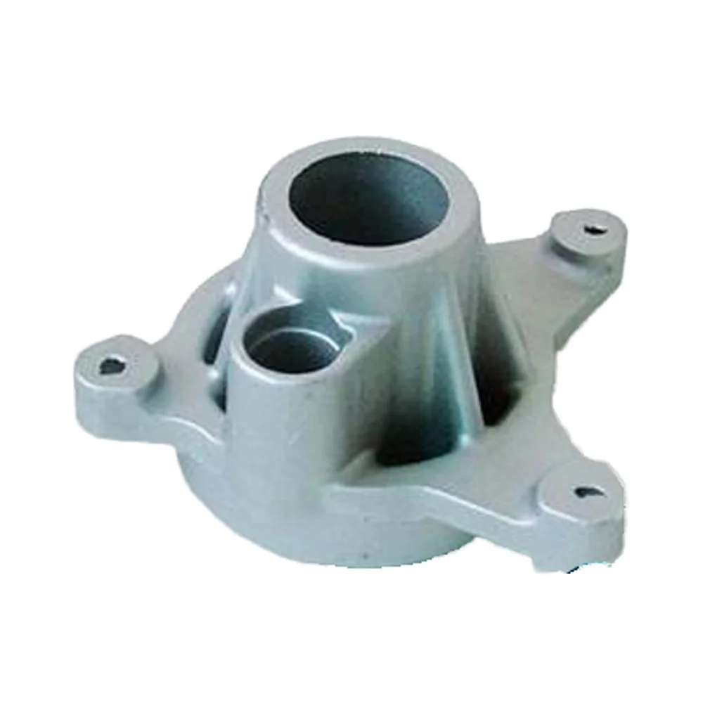
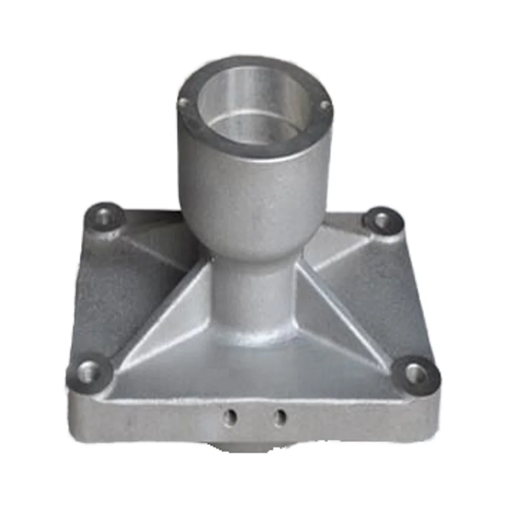
Develop the aluminum casting enquiry from the shell or tool requirement through the finished component. This OEM service includes selected die, sand or gravity casting, with mold development or 3D-printed shells, CNC machining and deburring. Define the actual deliverables at each stage so the development request and the production drawing describe the same ordered part.
Separate the Shell from the Metal Component
For a 3D-printed-shell proposal, identify the shell, tooling and casting boundaries explicitly. Select the full material grade and a suitable route for the geometry before assigning the CNC work. Stainless steel, steel alloy, bronze and brass can be requested as separate components rather than being treated as variations of the aluminum designation.
Distinguish Casting Tolerance from Finished Dimensions
The casting references include CT4–CT6, CT7–CT8 and CT9. Specify the governing convention, applicable dimensions and selected process for the actual casting instead of assuming every reference applies to every route. Finished tolerances and sizes follow the customer drawing, with machined interfaces identified separately from the casting condition.
Deburring belongs within the named processing scope for the chosen component. Agree the required final condition and the surfaces that will be used for material, dimensional and appearance approval. That keeps the shell-development and machining discussion focused on a part that can be checked against its drawing revision.
Align the Technical Files and Quality Scope
Drawing-data options include PDF, CAD, 3D, STP and STEP. Request applicable ISO9001:2000 and TS16949 documentation with its actual supplier or activity scope, alongside the quantity and acceptance requirements. A complete development enquiry identifies what is supplied as tooling, what is cast and which interfaces are finished before component approval.